Contents: Disassembly ⇩ Assembly ⇩
Disassembly
WARNING: Wear safety glasses when removing and installing the locking wheels and retaining ring.
CAUTION: When overhauling the steering gear, absolute cleanliness must be maintained.
NOTE: Do not overhaul the steering gear during the warranty period. NOTE: This procedure is for Adwest steering gear only.
1. Remove the steering gear from the vehicle.
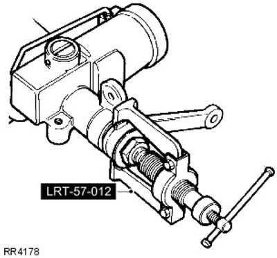
For more information, refer to the chapter: Steering gear (211-02 Power Steering, Removal and Installation). Mark the steering arm and steering gear for easy installation. Remove the steering arm using the LRT-57-012 puller. Loosen the steering arm mounting nut, but do not remove it until using the puller. Remove the dust cover from the secondary shaft.
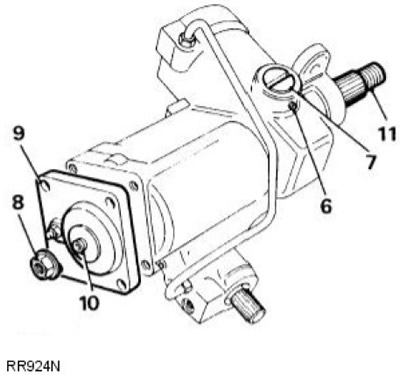
2. Drain the oil, remove the plugs and the bleed screw. Holding the steering gear over a suitable container, rotate the input shaft between the extreme lock positions to drain the oil. Replace the bleed screw.
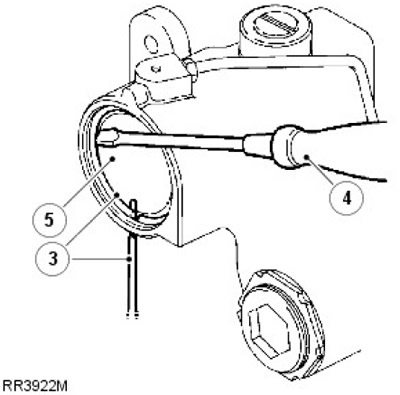
3. Rotate the retaining ring so that one end is 12 mm from the puller hole. Insert the punch into the hole in the cylinder and lift the retaining ring out of the groove in the cylinder.
4. Remove the retaining ring using a screwdriver.
5. Turn the input shaft (to the left lock position on left-hand drive vehicles, to the right lock position on right-hand drive vehicles) so that the piston pushes the cover out. Turn the input shaft completely in the opposite direction, applying pressure to the piston.
6. Remove the rack spacer adjuster from the set screw mount.
7. Remove the rack and pinion adjuster and gasket.
8. Remove the sector shaft adjuster lock nut.
9. Remove the four bolts from the sector shaft cover.
10. Screw in the sector shaft adjuster until the cover is removed.
11. Pull out the sector shaft.
12. Remove the piston; to make the operation easier, screw a bolt into the piston.
13. Remove the primary shaft dust cover.
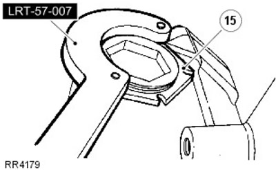
14. Remove the worm adjuster lock nut using the LRT-57-007 'C' spanner.
15. Remove the worm adjuster using the LRT-57-006 wrench.
16. Tap the splined end of the shaft to release the bearing.
17. Remove the bearing outer race and ball bearing assembly.
18. Remove the valve and worm assembly.
19.
NOTE: If difficulty is encountered, heat the race and bearing assembly. Cool the outer bearing race with a drift and tap the steering gear on a work bench.
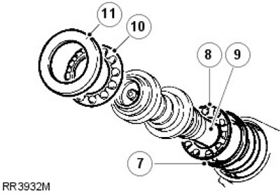
Remove the bearing inner race, outer race and washers. Save the washers for later assembly.
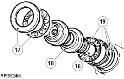
20.
CAUTION: Do not remove the sector shaft bearings from the race. No replacement parts are available. If the sector shaft bearings are worn, install a new steering gear.
Remove the retaining ring and seal from the sector shaft housing bore.
21.
CAUTION: It is recommended to use a seal remover to eliminate the risk of damage to the race which could result in oil leakage.
Remove the dust shield, snap ring and seal from the primary shaft housing bore.
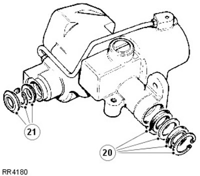
22. Discard all rubber seals, use new seals.
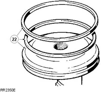
NOTE: The rubber seal is installed behind the plastic ring on the rack piston. Discard the seal and plastic ring.
23. Check the piston bore for scratches and signs of wear.
24. Inspect the supply line.
25. If there is any damage, install a new supply line. Tighten the connection to 22 Nm.
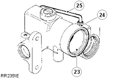
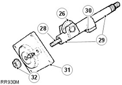
27. If there is lateral play on the roller, install a new sector shaft.
28. Check the condition of the adjusting screw threads. Check the axial play of the adjuster. Install a new adjuster if the axial play exceeds 0.15 mm.
29. Check for excessive wear on the shaft bearing areas.
30. Check for uneven or excessive wear on gear teeth.
31. Inspect the cover and bearing. If there is damage or wear, install a new steering gear.
32. The lock nut also functions as a seal. Install a new nut when reassembling.
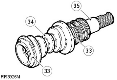
33. Check the bearing areas for wear. These areas should be smooth and free of dents.
34. Check the condition of the worm guide; it should be smooth, without any indentations.
35.
NOTE: If any signs of wear are present, a new valve and worm assembly must be installed.
Check the torsion bar assembly for wear. There should be no play between the input shaft and the torsion bar, or between the torsion bar and the worm.
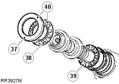
40. Repair of bearings and separators is performed by completely replacing the element as an assembly.
41. Check the thrust plate for scratches.
42. Check the regulator plate seat for wear.
43. Install a new sealing ring onto the rack and pinion adjuster.
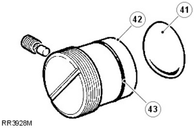
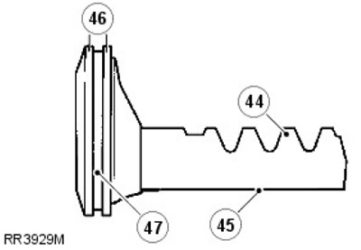
44. Check for excessive wear on the rack teeth.
45. Make sure that the bearing surface of the thrust plate is free of scratches and signs of wear.
46. Make sure that there are no burrs or damage on the outside diameters of the piston.
47. Check for scratches and damage on the seal and in the ring groove.
Assembly
1. Install a new ring on the piston. Heat the nylon seal and install it on the piston.
2. Insert the piston assembly into the cylinder; the rack pipe must be facing outward.
NOTE: When installing replacement seals, lubricate them with the recommended working fluid and ensure absolute cleanliness.
3. Install the seal, starting from the cuff side.
4. Install the protective washer.
5. Install the dust seal, finishing at the cuff side.
6. Install the retaining ring.
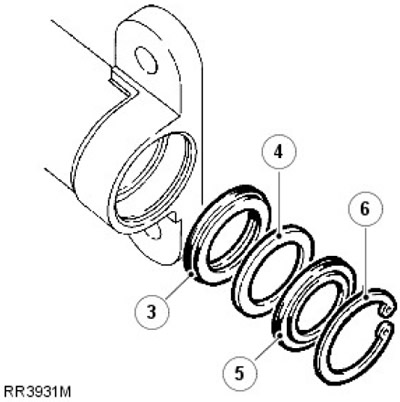
7. Install the original washers and inner bearing ring. Use Vaseline to ease installation.
NOTE: If original washers are not used, install 0.76mm washers.
8. Install the inner rings and bearings as an assembly.
9. Install the valve and worm assembly.
10. Install the outer separator and bearings as an assembly.
11. Install the outer bearing ring.
12. Install a new worm adjuster O-ring.
13. Screw the regulator into the housing without tightening.
14. Install, but do not tighten, the lock nut.
15. Turn the worm adjuster until the axial play is almost completely eliminated. Check that the bearing separators are seated correctly.
16. Measure the maximum torque of the valve and worm assembly using a torque wrench and LRT-57-025 slotted chuck.
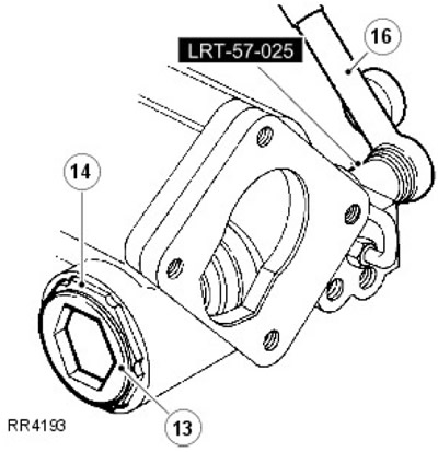
17. Screw in the worm adjuster while turning the shaft to increase the measured value to 0.56 Nm.
18. Loosen the worm adjuster by / of a turn. Screw in the worm adjuster to increase the measured value by 0.21-0.34 Nm, with the lock nut tightened - 100 Nm. Use the worm adjuster key LRT-57-006 and the lock nut key LRT-57-028.
19. Screw an auxiliary bolt into the piston to facilitate assembly.
20. Install the piston and rack so that the piston protrudes 70 mm relative to the outer end of the cylinder.
21. Install the sector shaft using a tool that prevents damage to the seals (LRT-57-021). Align the roller with the recess in the housing as shown in the figure. Push the sector shaft inward while rotating the input shaft so that the sector roller engages the worm.
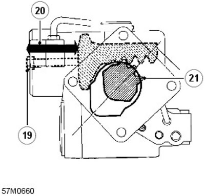
22. Install the rack adjuster and thrust plate to engage the rack. Back off the adjuster half a turn.
23. Loosely install the new nylon gasket and adjuster assembly set screw.
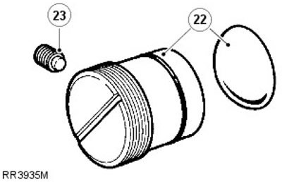
24. Install a new sealing ring on the cover.
25. Align the cover with the body.
26. Screw the cover assembly completely onto the sector shaft adjuster screw.
27. If necessary, loosen the sector shaft adjuster screw. Tap the installed cover to ensure its complete connection with the housing.
NOTE: Before tightening the fasteners, rotate the input shaft to check for free movement of the sector shaft roller in the valve worm. If initial resistance is felt, turn the adjuster screw approximately two turns clockwise.
28. Install the cover bolts. Tighten to 75 Nm.
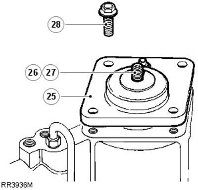
29. Install a new square section seal on the cover.
30. Remove the auxiliary bolt from the piston. Press the cover into the cylinder to expose the groove of the fastening ring.
31. Insert the retaining ring into the groove so that one end of the ring is 12 mm from the puller hole.
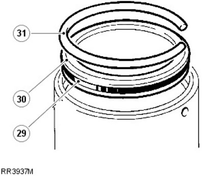
32. Install the steering arm and tighten it partially to ensure there is no gap between the steering arm and the sector shaft.
33. To set the worm to the central position, turn the input shaft to the extreme inner locking position (to the right lock position on left-hand drive vehicles, to the left lock position on right-hand drive vehicles). Rotate the input shaft back toward the center two full turns.
34. Now the block is centered and adjustments can be made.
35. Hold the input shaft and rock the steering arm to check for play. Continue rocking and slowly turn the sector shaft adjusting screw clockwise. Continue turning the adjusting screw until the play is almost completely eliminated.
36. Install and tighten the lock nut.
NOTE: It is important to center the steering gear before making any adjustments.
37. Check for maximum torque at one and a quarter turns each way from the center position using a torque wrench and LRT-57-025 slotted chuck. Turn the adjuster screw to obtain a center torque of 0.34 N·m plus torque at one and a quarter turns. Tighten the adjuster lock nut to 60 N·m (44 lbf/ft).
38. Turn the rack adjuster to increase the value measured in the previous step by 0.23-0.24 Nm. The final value may be less, but should not exceed 1.35 Nm.
39. Secure the rack and pinion adjuster with the set screw. Tighten to 5 Nm.
- 1. When turning the primary shaft between the extreme locking positions, the torque values should be maximum in the central position and evenly distributed relative to the central position.
- 2. This depends on the thickness of the washers installed between the inner bearing race and the race on the valve and worm assembly. If no major components have been replaced, the original thickness of the washers will ensure the correct maximum torque position.
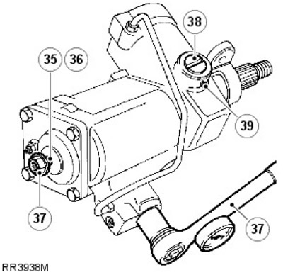
40. Turn the input shaft counterclockwise until it stops (the input shaft must face the mechanic).
41. Check the torque values between the extreme lock positions using a torque wrench and LRT-57-025 slotted chuck.
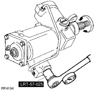
42. Also check for even engagement on both sides relative to the center.
43. Note where the largest values are recorded relative to the steering position. If the largest values are not recorded at the center of the stroke (in straight-ahead steering position), make the following adjustment:
- 1. If the torque peak occurs before the center position, increase the thickness of the washers.
- 2. If the torque peak occurs after the center position, reduce the thickness of the washers.
- 3. Washers of the following thicknesses are provided: 0.03 mm, 0.07 mm, 0.12 mm and 0.24 mm.
CAUTION: When installing new washers on the valve and worm, use extreme caution to avoid damaging the seals during assembly.
NOTE: Changing the shim thickness by 0.07mm moves the peak torque area by 1/4.
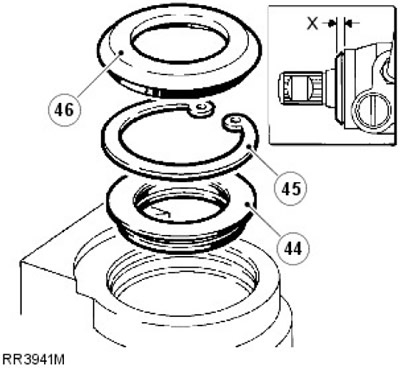
44. Insert the seal, starting from the cuff side, into the housing. Use a tool that prevents damage to the seals (LRT-57-016), and a seal installation tool (LRT-57-026). Check that the seal is installed to a depth of 4.75-5.00 mm relative to the front surface of the block.
45. Secure the seal with a retaining ring.
46. Apply PTFE grease to the inner seal of the dust shield. Install the dust shield using the LRT-57-027 tool. When installed correctly, the outer projection of the dust shield is 4.00-4.50 mm from the face of the block (dimension X).
47. Remove the steering arm. Apply PTFE grease to the inner seal of the dust cover mechanism and install it so that the outer seal is flush with the housing.
48. With the input shaft centered, align the timing marks on the steering arm and steering gear. Install the steering arm onto the steering gear using a new lock washer. Tighten to 176 Nm.
49. Install the steering gear.
For more information, refer to the chapter: Steering gear (211-02 Power Steering, Removal and Installation).
Comments on this article