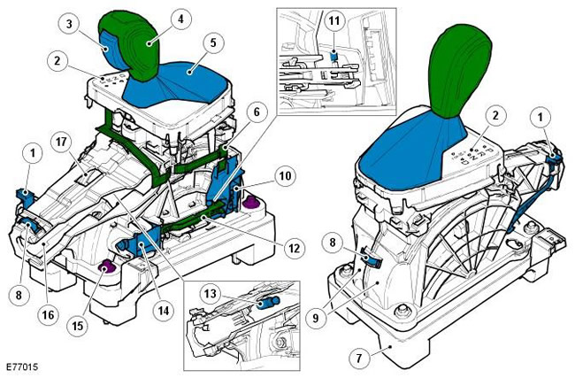
NOTE: Right hand drive vehicle shown
| Pos. | Spare part number | Name |
| 1 | - | Locking solenoid - Emergency release lever |
| 2 | - | Selector position LEDs |
| 3 | - | Selector lever button |
| 4 | - | Lever |
| 5 | - | Case |
| 6 | - | Flat cable and PCB connector |
| 7 | - | Selector lever support plate |
| 8 | - | Spring clamp |
| 9 | - | Gear Shift Housing - Left Side and Right Side |
| 10 | - | Gear Shift Module |
| 11 | - | Optical sensor installation mark |
| 12 | - | Sensor lever |
| 13 | - | Ball head pin for cable fastening |
| 14 | - | Gear shift lock solenoid |
| 15 | - | Bolt (4 pcs.) |
| 16 | - | Cable mounting opening |
| 17 | - | Cable adjustment/installation opening |
The selector lever assembly is located centrally on the transmission tunnel, between the front driver and passenger seats, and is secured to the transmission tunnel with four bolts. The selector lever assembly is a maintenance-free electromechanical unit used by the driver to select the desired transmission mode.
The driver's commands are transmitted from the selector lever via a cable to the transmission lever. A pin with a spherical head connects to the lever mechanism and ensures the connection of the cable.
There are 5 selector lever positions and 2 additional positions for manual "CommandShift™" mode:
- P (Parking) - Prevents vehicle movement by locking the gearbox
- R (Reverse) - Selectable only when the vehicle is stationary and the engine is idling
- N (Neutral position) - No torque is transmitted to the drive wheels
- D (Drive) - In this position, all six forward gears are used
- M/S (Sport Mode) - In this position, all six forward gears are used in the same way as in "D" mode, but to improve vehicle dynamics, upshifts occur at higher engine speeds, and downshifts also occur at higher engine speeds to improve engine braking.
- + / - (CommandShift™ Manual Mode) - Moving the selector lever in the + or - direction allows the driver to manually select a higher or lower gear from six possible forward gears.
The selector lever position is displayed on the LED selector position display and in the instrument cluster. In CommandShift™ mode, if a gear is selected but the TCM (Transmission Control Module) strategy does not allow that gear to be selected, the requested gear will be displayed first. The TCM will then engage the next available gear and display it on the display.
Sensor module
The sensor module is located on the left side of the selector lever. The sensor module is an intelligent unit that controls the operation of the selector lever position LEDs and the operation of the shift lock solenoid. The sensor module includes a printed circuit board (PCB) and Hall sensors that detect the selected position of the selector lever (M/S and + and - positions) using a magnet located in the lever mechanism. Signals from the Hall sensors are sent to the TCM from a connector on the sensor module via the LIN bus.
The main connector of the sensor module has 4 pins for the LIN bus: for ground, power, and neutral position input and output signals. The second connector is used to connect the flat cable from the selector position LED for night illumination and illumination of the position markings. The third connector is used to connect power and ground to the shift lock solenoid.
The sensor module also includes an optical sensor that detects that the selector lever is in the "P" parking position. The sensor is located behind the module housing and is not visible. The alignment marks on the sensor housing and the sensor lever must align when the selector lever is in the "P" parking position. If these two marks align, the optical sensor/parking position is adjusted correctly. This adjustment is set during assembly and does not require resetting under normal operating conditions.
Sport Mode/Manual Mode +/- CommandShift™
The sensor module contains Hall sensors that are used to activate the sport/manual mode, as well as sensors that provide +/- signals. When the selector lever is moved to the "manual/sport" position, a magnet located in the selector lever mechanism moves close to the M/S position Hall sensor located on the printed circuit board. This generates a signal that goes to the TCM, which in turn activates the sport mode.
When the selector is moved to the + or - position, the magnet approaches one of the Hall sensors located on either side of the M/S position Hall sensor. When a signal is received from the "+" or "-" sensor, the CommandShift™ manual mode is engaged. When the selector is released, the spring returns the selector lever to the center position. To exit CommandShift™ mode, move the selector to the "D" position.
Gear shift lock
The shift lock solenoid is located on the left side of the selector lever. The solenoid operates two locking levers that engage the lever mechanism and lock it in the Park "P" or Neutral "N" position. When the ignition is off, the solenoid is de-energized, locking the selector lever in the Park "P" position. If the selector lever is in any position other than Park "P", the remote key cannot be removed from the start control module until the lever is moved to the P position.
The shift lock solenoid is mechanically connected to the sensor module via the sensor lever. The movement of the solenoid is transmitted via the sensor lever to the sensor module, which detects the movement via the optical sensor. The movement of the sensor lever confirms to the sensor module that the solenoid is in the locked position. The sensor lever is adjusted via a ratchet mechanism. This adjustment is necessary to align the optical sensor, it is set at the factory and does not require further adjustment.
The shift lock solenoid locks the selector lever in the parking or neutral position to prevent accidental movement of the selector lever. The lock is released when the ignition is turned on and the brake pedal is pressed. The signal from the brake switch is transmitted via the high-speed CAN bus to the TCM, and then via the LIN bus to the sensor module. Upon receiving this signal, the sensor module, in accordance with its strategy, supplies power to the solenoid if the lever is in the parking position "P", or disconnects power to the solenoid if the lever is in the neutral position "N". Due to this, the mechanism is released from the lock.
If the selector lever remains in the "N" position for more than 3 seconds, the solenoid will be energized and the selector lever will be locked in the "N" position. In this condition, to move the selector lever from the "N" position, it is necessary to press the brake pedal. This prevents the selector lever from being inadvertently moved to the "D" or "R" position, and applying the brake prevents the vehicle from creeping when a gear is engaged. Even when the brake pedal is pressed, the TCM prohibits moving the selector lever from the "P" or "N" position if the engine speed exceeds 2500 rpm.
If the shift lock solenoid, sensor module, brake switch, or associated wiring is faulty, the emergency release lever can be used to disengage the lock mechanism. To access the emergency release lever, remove the shift selector trim from the floor console using a hand tool. The trim must be lifted to access the release lever, which is located at the front of the shift selector assembly and is painted yellow for easy identification.
NOTE: The selector lever cannot be moved from the "P" park position if the ignition is off, except when using the emergency release lever.
[The material was taken from a website www.lrman.ru]
Comments on this article