Special tool
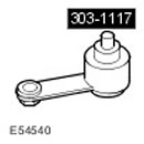 Injection Timing Rod - Automatic Transmission 303-1117 Injection Timing Rod - Automatic Transmission 303-1117 | 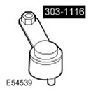 Injection Timing Rod - Manual Transmission 303-1116 Injection Timing Rod - Manual Transmission 303-1116 | 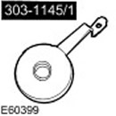 Camshaft Pulley Locking Device 303-1145/1 Camshaft Pulley Locking Device 303-1145/1 |
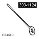 Holder - Front Camshaft Pulley 303-1124 Holder - Front Camshaft Pulley 303-1124 | 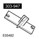 Faceplate Locking Tool 303-947 Faceplate Locking Tool 303-947 | 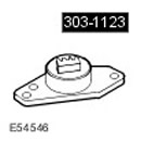 Flywheel Locking Device 303-1123 Flywheel Locking Device 303-1123 |
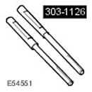 Injection Timing Rod - Camshaft Pulley 303-1126 Injection Timing Rod - Camshaft Pulley 303-1126 |
Assembly
1.
NOTE: Clean the mating surfaces of the components.
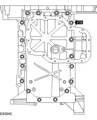
NOTE: The oil pan extension must be bolted to the crankshaft main bearing housing within 20 minutes after applying the sealant.
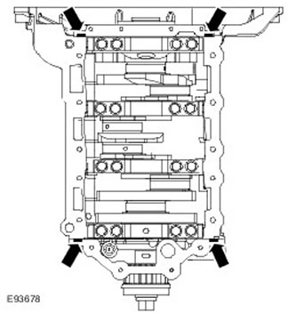
Apply an 8 mm bead of sealant to the areas of the cylinder block shown. Use sealant WSS-M4G323-A4-RTV.
2.
NOTE: Clean the mating surfaces of the components.
Install the oil pan extension.
- Install a new gasket.
- Screw in the bolts, but do not tighten them.
3.
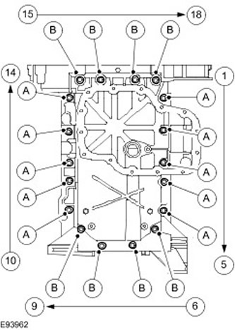
CAUTION: Tighten the bolts in 2 steps in the sequence shown.
Secure the oil pan extension.
- 1. Tighten bolts A to 10 Nm. Tighten bolts B to 4 Nm.
- 2. Tighten bolts A to 24 Nm. Tighten bolts B to 10 Nm.
4.
NOTE: Lubricate new seals with clean engine oil.
NOTE: Clean the elements.
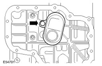
Install the mesh filter and oil pump oil pickup pipe.
- Clear the elements.
- Install new O-rings.
- Tighten the bolt to 10 Nm.
5.
NOTE: Clean the mating surfaces of the components.
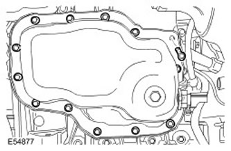
Install the oil pan.
- Install a new gasket.
- Tighten the bolts evenly and gradually to 10 Nm.
6. Install the high-pressure fuel pump. Tighten the bolts to 23 Nm.
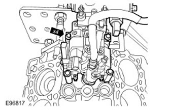
7.
CAUTION: Make sure the gasket is installed correctly.
NOTE: Clean the mating surfaces of the components.
Install the oil cooler assembly.
- Install a new gasket.
- Install a new O-ring.
- Tighten the bolts to 10 Nm.
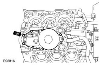
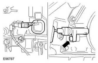
8. Install the crankshaft position (CKP) sensor.
- Tighten the bolt to 5 Nm.
- Connect the electrical connector.
- Replace the cover of the access hole.
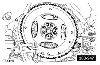
9.
CAUTION: Tighten the bolts in a crisscross pattern.
CAUTION: Tighten the bolts in the order shown in the illustration.
NOTE: Clean the mating surfaces of the components.
Install the faceplate.
- Lock the faceplate with a special tool.
- Step 1: Tighten the bolts to 50 Nm.
- Step 2: Tighten the bolts to 45 degrees.
- Step 3: Tighten the bolts an additional 45 degrees.
- Remove the special tool.
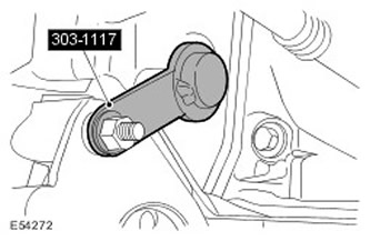
10. Lock the faceplate with a special tool.
- Turn the crankshaft clockwise to align the crankshaft adjustment hole in the flywheel or faceplate with the hole in the cylinder block.
- Screw in the starter bolt to secure the special tool.
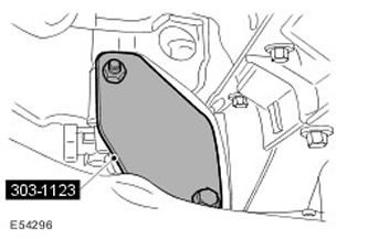
11. Install the special tool.
12.
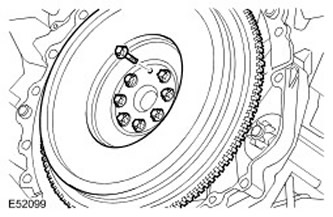
CAUTION: Tighten the bolts in a crisscross pattern.
CAUTION: Tighten the bolts in the order shown in the illustration.
NOTE: Clean the mating surfaces of the components.
Install the flywheel.
- Step 1: Tighten the bolts to 50 Nm.
- Step 2: Tighten the bolts to 45 degrees.
- Step 3: Tighten the bolts an additional 45 degrees.
13.
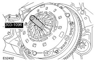
CAUTION: Install the clutch disc with the 'TRANSMISSION SIDE' marking facing (gearbox side) to the clutch housing.
CAUTION: Use a special tool to align the parts.
CAUTION: Tighten the bolts gradually in a criss-cross pattern.
NOTE: Clean the mating surfaces of the components.
Using a special tool, install the clutch slave and pressure plates. Tighten the bolts to 25 Nm.
14. Remove the special tool.
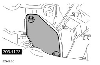
15. Using the special tool, lock the flywheel.
- Turn the crankshaft clockwise to align the crankshaft adjustment hole in the flywheel or faceplate with the hole in the cylinder block.
- Screw in the starter bolt to secure the special tool.
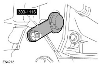
16. Check the surface of the left cylinder head for deformation, measuring in the longitudinal and transverse directions and diagonally.
17.
NOTE: The cylinder head gasket must be installed on the cylinder block studs.
NOTE: Clean the mating surfaces of the components.
Install a new left cylinder head gasket.
18.
CAUTION: Use caution when installing the cylinder head. Failure to follow this instruction may result in damage to the cylinder block, cylinder head or cylinder head gasket.
CAUTION: Use new bolts.
NOTE: The cylinder head gasket must be installed on the cylinder block studs.
NOTE: Make sure the cylinder head is installed in its original position.
NOTE: Tighten the bolts in 4 steps in the sequence shown.
NOTE: Clean the mating surface of the element.
Install the left row cylinder head assembly.
- Step 1: Tighten the bolts to 20 Nm.
- Step 2: Tighten the bolts to 40 Nm.
- Step 3: Tighten the bolts to 80 Nm.
- Step 4: Tighten the bolts another 180 degrees.
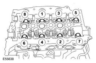
19. Check the surface of the right cylinder head for deformation, measuring in the longitudinal and transverse directions and diagonally.
20.
NOTE: The cylinder head gasket must be installed on the cylinder block studs.
NOTE: Clean the mating surfaces of the components.
Install a new right cylinder head gasket.
21.
CAUTION: Use caution when installing the cylinder head. Failure to follow this instruction may result in damage to the cylinder block, cylinder head or cylinder head gasket.
CAUTION: Use new bolts.
NOTE: The cylinder head gasket must be installed on the cylinder block studs.
NOTE: Make sure the cylinder head is installed in its original position.
NOTE: Tighten the bolts in the sequence shown in four steps.
Install the right cylinder head assembly.
- Stage 1: Tighten to 20 Nm.
- Stage 2: Tighten to 40 Nm.
- Stage 3: Tighten to 80 Nm.
- Stage 4: Tighten another 180 degrees.
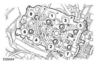
22. Install the secondary timing chain to the right-hand cylinder bank camshafts.
23.
CAUTION: Do not release the secondary timing chain tensioner retaining pin until all camshaft bearing caps have been installed.
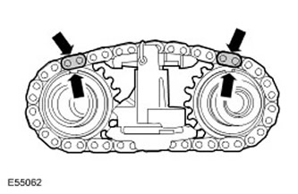
Install the right bank secondary timing chain tensioner. Align the marks on the camshafts with the marks on the secondary timing chain.
24.
NOTE: Clean the elements.
NOTE: Install a new seal.
Install the right cylinder bank camshafts complete with the secondary timing chain tensioner. Lubricate the camshaft journals and cams.
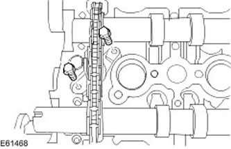
25. Secure the secondary timing chain tensioner for the right cylinder bank. Tighten the bolts to 10 Nm.
26.
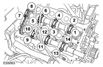
CAUTION: Tighten the bolts evenly in 3 stages in the sequence shown.
NOTE: Do not install the two exhaust camshaft end bearing caps at this time.
NOTE: Clean the mating surfaces of the components.
Install the right bank camshaft bearing caps.
- Stage 1: Tighten to 1 Nm.
- Stage 2: Tighten to 5 Nm.
- Stage 3: Tighten to 10 Nm.
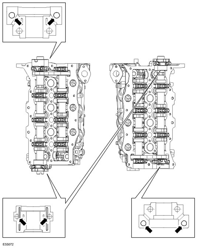
27. Apply sealant to the right exhaust camshaft end bearing cap as shown in the illustration.
28.
CAUTION: Tighten the bolts in the sequence shown.
NOTE: Clean the mating surfaces of the components.
Install the right bank exhaust camshaft end bearing caps.
- Stage 1: Tighten to 1 Nm.
- Stage 2: Tighten to 5 Nm.
- Stage 3: Tighten to 10 Nm.
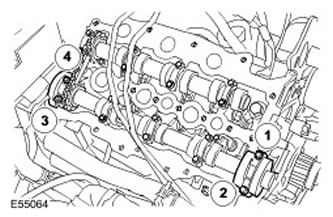
29. Release the piston of the secondary timing chain tensioner of the right cylinder bank. Remove the locking pin.
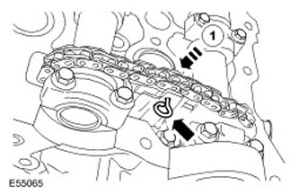
30. Install the secondary timing chain to the left cylinder bank camshafts.
31.
CAUTION: Do not release the secondary timing chain tensioner retaining pin until all camshaft bearing caps have been installed.
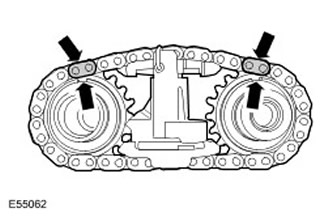
Install the tensioner of the secondary timing chain of the left cylinder bank. Align the marks on the camshafts with the marks on the secondary timing chain.
32.
NOTE: Clean the elements.
NOTE: Install new seals.
Install the left-hand cylinder bank camshafts complete with the secondary timing chain tensioner. Lubricate the camshaft journals and cams.
33. Secure the tensioner of the secondary timing chain of the left cylinder bank. Tighten the bolts with a torque of 10 Nm.
34.
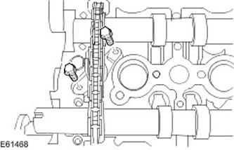
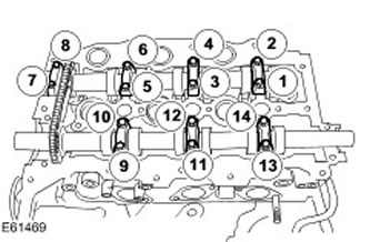
CAUTION: Tighten the bolts evenly in 3 stages in the sequence shown.
NOTE: Do not install the two exhaust camshaft end bearing caps at this time.
NOTE: Clean the mating surfaces of the components.
Install the left bank camshaft bearing caps.
- Stage 1: Tighten to 1 Nm.
- Stage 2: Tighten to 5 Nm.
- Stage 3: Tighten to 10 Nm.
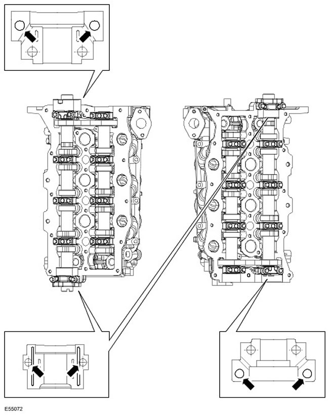
35. Apply sealant to the 2 left exhaust camshaft end bearing caps as shown in the figure.
36.
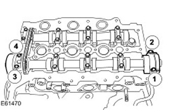
CAUTION: Tighten the bolts in the sequence shown.
NOTE: Clean the mating surfaces of the components.
Install the left bank exhaust camshaft end bearing caps.
- Step 1: Tighten the bolt to 1 Nm.
- Step 2: Tighten the bolt to 5 Nm.
- Step 3: Tighten the bolt to 10 Nm.
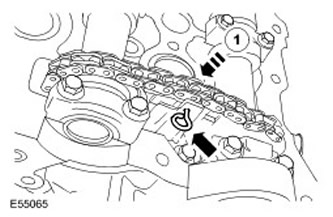
37. Release the piston of the secondary timing chain tensioner of the left cylinder bank. Remove the locking pin.
38. Install the rear cover of the high-pressure fuel pump drive belt. Tighten the bolts to 10 Nm.
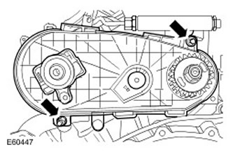
39. Install the rear camshaft pulley. Screw in a new camshaft pulley bolt.
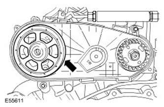
40. Install the special tool on the rear camshaft pulley. Screw in and tighten the bolt.
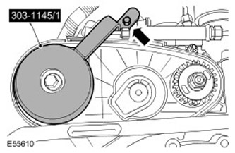
41.
CAUTION: Tighten the bolts in the order shown in the illustration.
Secure the rear camshaft pulley.
- Step 1: Tighten the bolt to 40 Nm.
- Step 2: Tighten the bolt to 75 Nm.
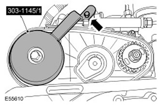
43.
CAUTION: Do not install the new fuel injection pump belt onto the pulleys with the tensioner installed. Failure to follow this instruction may result in damage to the fuel injection pump belt.
NOTE: The high pressure fuel pump rotates counterclockwise when viewed from the rear of the engine.
Install a new high pressure fuel pump belt.
44.
CAUTION: Do not remove the fuel injection pump belt tensioner retaining pin until the tensioner is completely installed.
CAUTION: Make sure that the tab of the fuel injection pump drive belt tensioner is correctly positioned relative to the rear cover of this belt. Failure to do so may result in engine damage.
Install a new high pressure fuel pump belt tensioner.
- Insert the tab on the new fuel injection pump belt tensioner into the fuel injection pump rear cover.
- Tighten the bolt to 25 Nm.
- Remove the high pressure fuel pump drive belt tensioner locking pin and discard it.
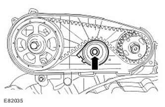
45. Install the high pressure fuel pump drive belt cover.
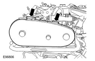
46. Install the cooling fan drive hub bearing. Tighten the bolts to 90 Nm.
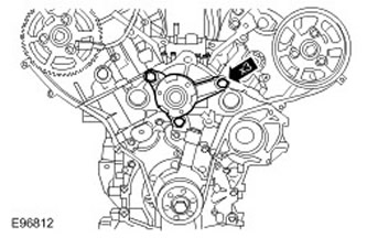
47.
CAUTION: Use new bolts.
NOTE: Left side shown, same for right side.
NOTE: Clean the mating surfaces of the components.
Using the special tool, install the 2 camshaft pulley hubs.
- Stage 1: Tighten to 80 Nm.
- Stage 2: Tighten another 90 degrees.
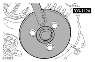
48. Install the 2 exhaust camshaft pulleys. Install the bolts, but do not tighten them completely yet.
49. Install the special tools. Turn the camshafts.
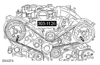
50. Install 2 timing belt idler pulleys.
- Install a plastic shield behind the upper idler pulley.
- Tighten the bolts to 45 Nm.
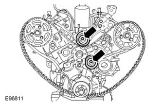
51. Turn both camshaft pulleys clockwise.
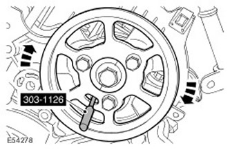
52. Install the new timing belt tensioner. Screw in the new bolt, but do not tighten it all the way yet.
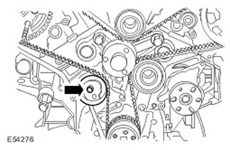
53.
CAUTION: The camshaft pulleys must remain in the position obtained by turning them clockwise.
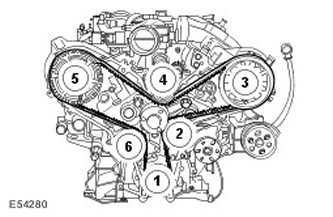
Install a new timing belt.
- Starting from the crankshaft pulley, install the timing belt in a counterclockwise direction in the sequence shown.
- Step 1: Place the timing belt on the crankshaft pulley.
- Step 2: Place the timing belt on the idler pulley.
- Step 3: Place the timing belt on the left camshaft pulley.
- Step 4: Place the timing belt on the idler pulley.
- Step 5: Install the timing belt onto the right camshaft pulley.
- Step 6: Attach the timing belt to the tensioner.
[Information obtained from the website LRMAN.RU]
54.
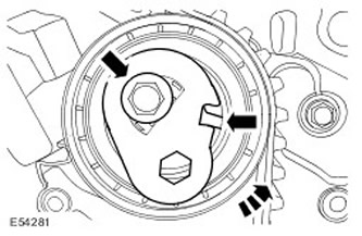
CAUTION: Make sure the timing belt tensioner window is aligned with the groove.
Tighten the timing belt.
- Turn the tensioner assembly counterclockwise.
- Tighten the bolt to 24 Nm.
55.
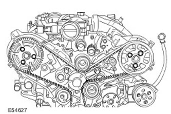
CAUTION: Do not use special tools to lock the camshafts. Failure to do so may result in damage to the engine or special tools.
Secure the camshaft pulleys.
- Using a suitable tool, hold the camshaft pulley center bolts.
- Tighten the bolts to 23 Nm.
56. Remove the special tools.
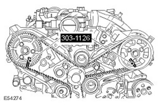
57. Remove the special tool. Unscrew the bolt.
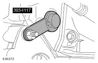
58. Remove the special tool. Unscrew the bolt.
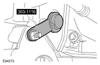
59. Turn the engine two full turns clockwise.
60. Lock the faceplate with the special tool. Screw in the starter bolt to secure the special tool.
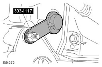
61. Using the special tool, lock the flywheel. Screw in the starter bolt to secure the special tool.
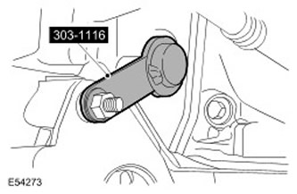
62. Install the special tools on the exhaust camshaft pulleys.
- If the special tool is not installed correctly, repeat the timing belt installation procedure.
- Remove the special tools from the camshaft pulleys.
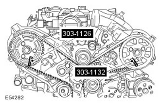
63. Remove the special tool. Unscrew the bolt.
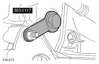
64. Remove the special tool. Unscrew the bolt.
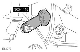
65.
NOTE: Remove and discard plugs.
Install a new fuel injector return line.
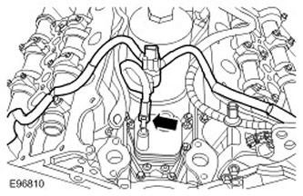
66.
NOTE: Remove and discard plugs.
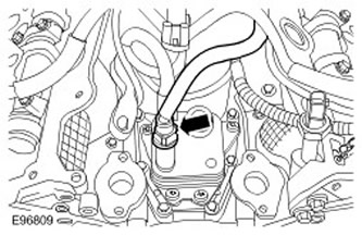
Connect the fuel line to the fuel cooler.
67.
NOTE: Install new O-rings.
NOTE: Clean the mating surfaces of the components.
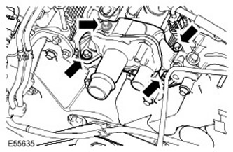
Install the cylinder head coolant outlet assembly. Tighten the bolts to 10 Nm.
68.
NOTE: Install new O-rings.
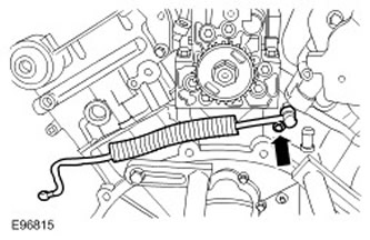
Install the turbocharger oil feed line. Tighten the bolts to 10 Nm.
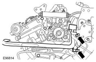
69. Install the ventilation duct.
- Secure the clamp.
- Tighten the bolt to 10 Nm.
70.
NOTE: Clean the mating surfaces of the components.
NOTE: Install a new gasket.
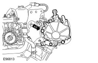
Install the brake system vacuum pump.
- Install the bracket.
- Tighten the bolts to 23 Nm.
71.
NOTE: Clean the mating surfaces of the components.
NOTE: Install a new gasket.
Install the right valve cover.
- Tighten the bolts to 10 Nm.
- Secure the glow plug electrical connector to the valve cover.
- Secure the knock sensor (KS) electrical connector to the valve cover.
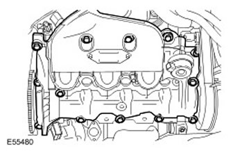
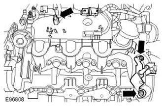
72. Screw in the mounting studs of the right engine cover.
- Install the bracket.
- Tighten the nut to 10 Nm.
- Tighten the bolt to 10 Nm.
73.
NOTE: Clean the mating surfaces of the components.
NOTE: Install a new gasket.
Install the left valve cover.
- Tighten the bolts to 10 Nm.
- Secure the KS electrical connector to the valve cover.
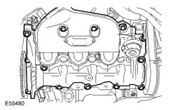
74. Screw in the mounting studs of the left engine cover.
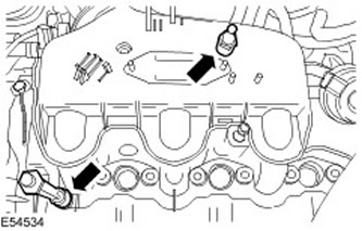
75. Install the fuel rail brackets. Tighten the bolts to 23 Nm.
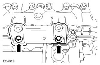
76. Install the fuel rails. Install the bolts, but do not tighten them completely yet.
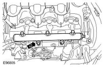
77.
NOTE: Remove and discard plugs.
Install a new right fuel rail high pressure fuel supply line.
- Tighten the fuel injection manifold mounting bolts to 23 Nm.
- Step 1: Tighten the high pressure fuel supply line union on the intermediate fuel rail side to 15 Nm.
- Step 2: Tighten the high pressure fuel supply line union on the fuel rail side to 15 Nm.
- Step 3: Tighten the high pressure fuel supply line union on the intermediate fuel rail side to 30 Nm.
- Step 4: Tighten the high pressure fuel supply line union on the fuel rail side to 30 Nm.
- Secure the clamp.
NOTE: Remove and discard plugs.
Install a new left fuel rail high pressure fuel supply line.
- Tighten the fuel injection manifold mounting bolts to 23 Nm.
- Step 1: Tighten the high pressure fuel supply line union on the intermediate fuel rail side to 15 Nm.
- Step 3: Tighten the high pressure fuel supply line union on the intermediate fuel rail side to 30 Nm.
- Step 2: Tighten the high pressure fuel supply line union on the fuel rail side to 15 Nm.
- Step 4: Tighten the high pressure fuel supply line union on the fuel rail side to 30 Nm.
- Secure the clamp.
NOTE: Remove and discard plugs.
Install new high pressure fuel supply line to intermediate fuel rail.
- Stage 1: Tighten the high pressure fuel supply line union on the high pressure fuel pump side to 15 Nm.
- Step 2: Tighten the high pressure fuel supply line union on the intermediate fuel rail side to 15 Nm.
- Step 3: Tighten the high pressure fuel supply line union on the high pressure fuel pump side to 30 Nm.
- Step 4: Tighten the high pressure fuel supply line union on the intermediate fuel rail side to 30 Nm.
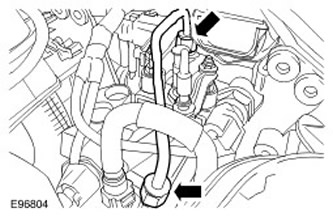
80.
NOTE: Remove and discard plugs.
Install a new right fuel rail high pressure fuel supply line.
- Tighten the fuel injection manifold mounting bolts to 23 Nm.
- Stage 1: Tighten the high pressure fuel supply line union on the high pressure fuel pump side to 15 Nm.
- Step 2: Tighten the high pressure fuel supply line union on the fuel rail side to 15 Nm.
- Step 3: Tighten the high pressure fuel supply line union on the high pressure fuel pump side to 30 Nm.
- Step 4: Tighten the high pressure fuel supply line union on the fuel rail side to 30 Nm.
- Secure the clamp.
NOTE: Remove and discard plugs.
Install a new left fuel rail high pressure fuel supply line.
- Tighten the fuel injection manifold mounting bolts to 23 Nm.
- Stage 1: Tighten the high pressure fuel supply line union on the high pressure fuel pump side to 15 Nm.
- Step 2: Tighten the high pressure fuel supply line union on the fuel rail side to 15 Nm.
- Step 3: Tighten the high pressure fuel supply line union on the high pressure fuel pump side to 30 Nm.
- Step 4: Tighten the high pressure fuel supply line union on the fuel rail side to 30 Nm.
- Secure the clamp.
CAUTION: Do not disassemble the fuel injectors or clean their nozzles, even with ultrasound. Always install new fuel injectors when necessary.
CAUTION: Do not use tools to install the new fuel return line retaining clip. Failure to do so may result in damage to the retaining clip.
Install a new fuel injector clamp.
- 1. Install the fuel injector clamp spacer sleeve.
- 2. Install the new fuel return line retaining clip.
- 3. Install a new sealing washer.
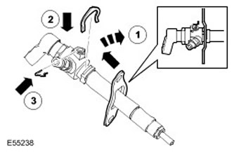
83. Install the fuel injector. Tighten the bolts to 10 Nm.
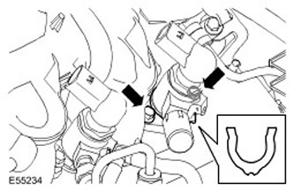
84. Install the remaining fuel injectors.
85.
CAUTION: Do not allow the fittings to hit the sealing lenses of the high pressure fuel supply line, as this may cause damage to the ends of the fuel line and allow dirt to enter the fuel injection system.
CAUTION: When fitting, apply pressure to the high pressure fuel supply line to keep the sealing lenses in contact with the fuel injector cones and fuel rail.
NOTE: Remove and discard plugs.
Install new high pressure fuel injector feed lines.
- Step 1: Tighten the high pressure fuel supply line union on the injector side to 15 Nm.
- Step 2: Tighten the high pressure fuel supply line union on the fuel rail side to 15 Nm.
- Step 3: Tighten the high pressure fuel supply line union on the injector side to 30 Nm.
- Step 4: Tighten the high pressure fuel supply line union on the fuel rail side to 30 Nm.
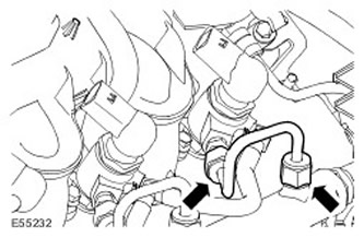
86.
CAUTION: Make sure the fuel return line clamp is properly installed on the fuel injector before installing the fuel return line.
Connect the fuel return line to the fuel injectors. Apply a thin layer of petroleum jelly to the O-rings of the fuel return line.
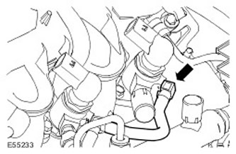
87. Install the engine wiring harness.
- Tighten the nut to 10 Nm.
- Secure the clamps.
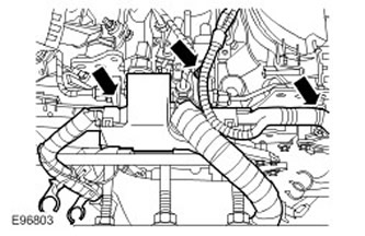
88. Connect the electrical connectors of the high pressure fuel pump.
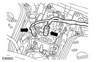
89. Connect the fuel rail pressure (FRP) sensor electrical connector.
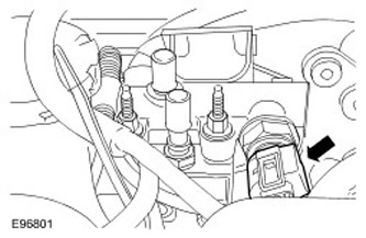
90. Install the engine crankcase ventilation oil separator. Connect and secure the 2 ventilation hoses.
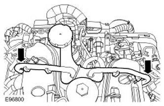
91. Connect the fuel temperature sensor electrical connector.
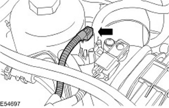
92.
NOTE: Left side shown, same for right side.
Connect 2 KS electrical connectors.
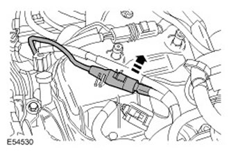
93. Connect the electrical connector of the engine oil temperature sensor. Secure the wiring harness clamp.
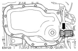
94. Connect the camshaft position (CMP) sensor electrical connector. Secure the wiring harness clamp.
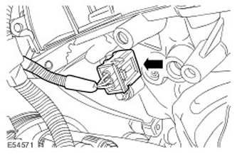
95.
NOTE: Right side shown, same for left side.
Connect the electrical connectors of the six fuel injectors. Secure the 4 wiring harness clamps.
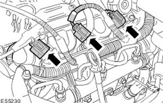
96. Connect the electrical connector of the engine oil pressure (EOP) sensor. Secure the wiring harness clamp.
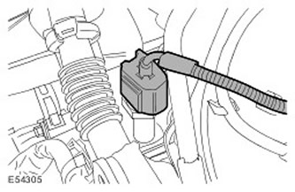
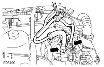
97. Install 2 low pressure fuel lines.
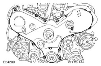
98. Install the timing belt cover. Tighten the bolts to 10 Nm.
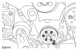
99. Install the crankshaft pulley. Tighten the bolts to 14 Nm.
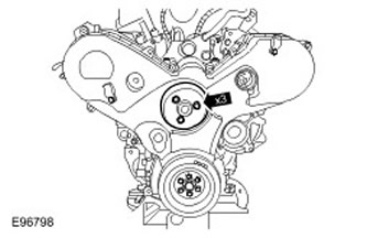
100. Install the cooling fan pulley. Tighten the bolts to 23 Nm.
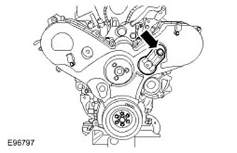
101. Install the auxiliary drive belt idler pulley. Tighten the bolt to 47 Nm.
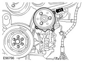
102.
NOTE: Clean the mating surfaces of the components.
NOTE: Install a new O-ring.
Install the coolant pump. Tighten the bolts to 10 Nm.
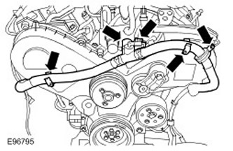
103. Install the exhaust gas recirculation valve (EGR) coolant line.
- Screw in the bolt.
- Connect the electrical connector.
- Secure with two clamps.
- Secure the clamp.
104.
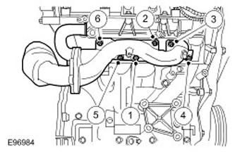
CAUTION: Use new nuts.
NOTE: Tighten the nuts in the sequence shown.
NOTE: Install a new gasket.
Install the right exhaust manifold assembly with the exhaust bypass pipe. Tighten the nuts to 24 Nm.
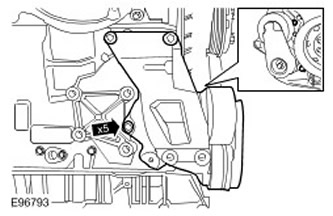
105. Install the generator bracket. Tighten the bolts to 23 Nm.
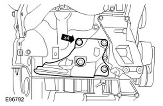
106. Install the right engine mount bracket. Tighten the bolts to 110 Nm.
107. Install the right exhaust manifold heat shield. Tighten the bolts to 10 Nm.
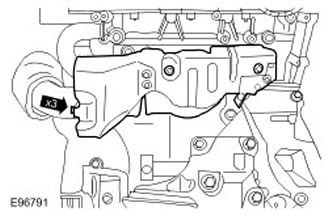
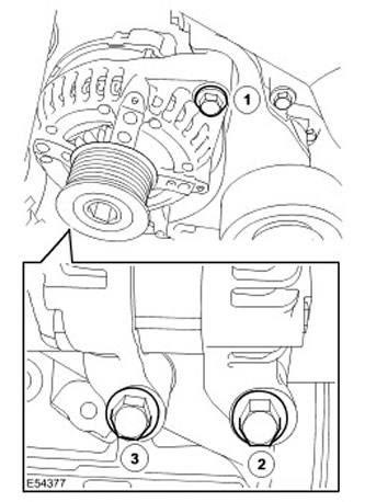
108.
CAUTION: Tighten the bolts in the sequence shown.
Install the generator. Tighten the bolts to 47 Nm.
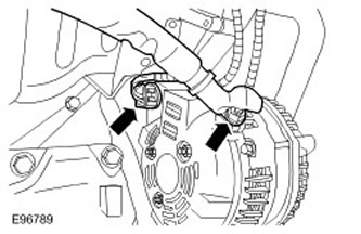
109. Connect the generator electrical connectors.
- Tighten the nut to 12 Nm.
- Move the rubber pad.
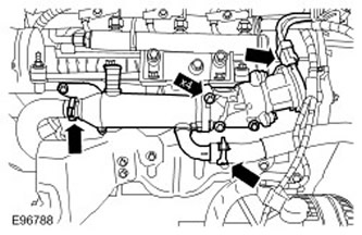
110. Install the right EGR valve and heat exchanger assembly.
- Tighten the bolts to 10 Nm.
- Connect the coolant hose and secure with a clamp.
- Connect the electrical connector.
- Install and secure the new clamp.
111.
NOTE: Install a new O-ring.
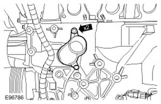
Install the cylinder block coolant inlet pipe. Tighten the bolts to 10 Nm.
112.
CAUTION: Use new nuts.
NOTE: Tighten the nuts in the sequence shown.
NOTE: Install a new gasket.
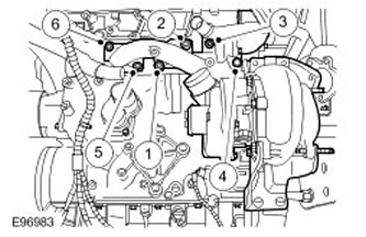
Install the left exhaust manifold with turbocharger. Tighten the nuts to 24 Nm.
113.
CAUTION: Use new nuts.
NOTE: Install a new gasket.
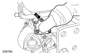
Attach the exhaust bypass pipe to the left exhaust manifold. Tighten the nuts to 24 Nm.
114.
NOTE: Remove and discard plugs.
NOTE: Install new sealing washers.
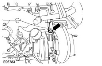
Connect the turbocharger oil supply line. Tighten the hollow bolt to 30 Nm.
115. Secure the turbocharger support bracket. Tighten the bolts to 23 Nm.
116.
NOTE: Remove and discard plugs.
NOTE: Install a new O-ring.
NOTE: Install a new gasket.
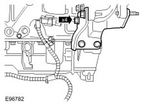
Install the turbocharger oil return line. Tighten the bolts to 10 Nm.
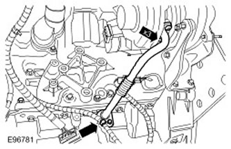
117. Install the turbocharger heat shield. Tighten the bolts to 10 Nm.
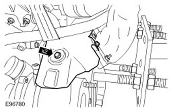
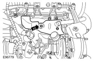
118. Install the left exhaust manifold heat shield. Tighten the bolts to 10 Nm.
119. NOTE: Install a new clamp.
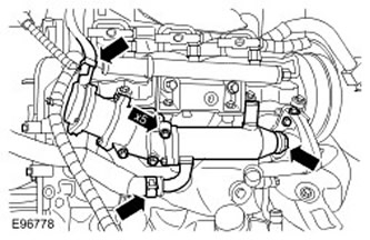
Install the EGR valve assembly with the left cylinder bank heat exchanger.
- Install the support bracket.
- Tighten the bolts to 10 Nm.
- Connect the coolant hose and secure with a clamp.
- Connect the electrical connector.
- Install and secure the clamp.
120.
NOTE: Remove and discard plugs.
NOTE: Install a new O-ring.
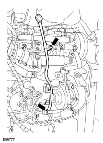
Install the dipstick and oil level indicator tube.
- Tighten the bolt to 10 Nm.
- Secure the wiring harness clamp.
121. Install the left engine mount bracket. Tighten the bolts to 110 Nm.
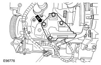
122. Install the air conditioning compressor bracket. Tighten the bolts to 23 Nm.
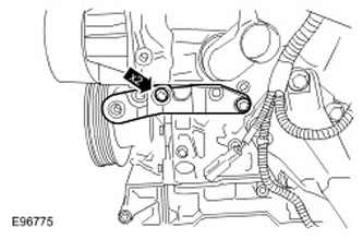
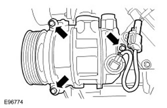
123. Install the air conditioning compressor.
- Tighten the bolts to 23 Nm.
- Connect the electrical connector.
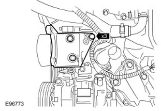
124. Install the power steering pump bracket. Tighten the bolts to 23 Nm.
125. Remove the engine from the engine stand.
126. Install the engine. For more information, refer to Engine - Vehicles equipped with: Automatic transmission (12.41.01.99). For more information, please refer to Engine - Vehicle equipped with: Manual transmission (12.41.01.99).
127. Fill the engine with the recommended oil to the specified level. For more information, refer to Draining and filling engine oil (12.60.05).
Comments on this article