Contents: Dismantling ⇩ Installation ⇩
Dismantling
1. Remove the cylinder head.
ENGINE - MODIFICATION K, volume 1.8, Piston group, Cylinder head gasket.
2. Remove the rear crankshaft oil seal.
ENGINE - MODIFICATION K, volume 1.8, Piston group, Replacement of rear crankshaft oil seal.
3. Remove the pinion gear from the crankshaft.
4. Remove and discard the oil filter.
MAINTENANCE, Engine oil and oil filter - K1.8.
5. Remove the oil pump.
ENGINE - MODIFICATION K, volume 1.8, Piston group, Oil pump overhaul.
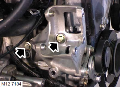
6. Unscrew the 2 bolts securing the power steering pump bracket to the cylinder block and remove the bracket.
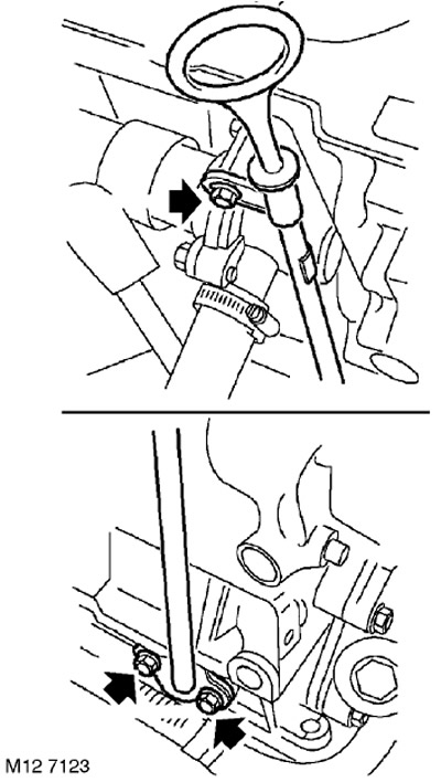
7. Remove the oil dipstick.
8. Remove the bolt securing the thermostat housing and the oil dipstick housing to the cylinder block.
9. Unscrew the 2 bolts securing the oil dipstick housing to the cylinder block.
10. Remove the dipstick cover and discard the gasket.
11. Remove the transmission pan.
ENGINE - MODIFICATION K, volume 1.8, Piston group, Oil pan.
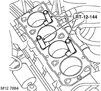
12. Unscrew the bolts from the LRT-12-144 cylinder liner fasteners and remove the fasteners.
CAUTION: Store the cylinder head bolts in the order they were on the assembled engine. Do not rotate the crankshaft after removing the cylinder liner fasteners.
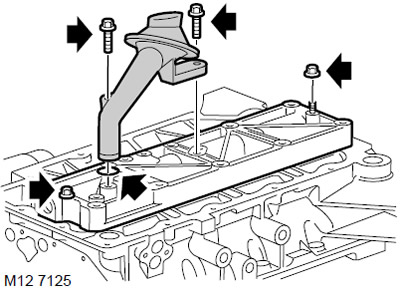
13. Unscrew the 2 bolts securing the oil receiver to the oil distribution cover.
14. Remove the oil receiver with the mesh filter.
15. Remove the O-ring from the oil receiver and discard it.
16. Unscrew the 2 nuts securing the oil distribution cover to the integral main bearing cover and remove the cover.
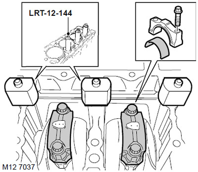
17. Install the LRT-12-144 cylinder liner fasteners with the nylon nuts included in the fastener kit. The base of the cylinder liner fasteners should not protrude above the cylinder bore. Screw in the cylinder head fastening bolts until the cylinder liner fasteners are securely held.
CAUTION: The bolts used must be screwed into the same sockets in which they were located on the assembled engine.
18. Temporarily install the timing belt drive gear and the front crankshaft pulley, screw in the front pulley mounting bolt with a washer.
19. Mark the connecting rod caps for subsequent assembly.
20. Rotating the crankshaft clockwise, set the pistons of cylinders 2 and 3 to the bottom dead center.
21. Unscrew the 4 fitting bolts (the bolt that also functions as a pin) and remove the caps from the connecting rods of the 2nd and 3rd cylinders. Lay out the bolts and caps in the order in which they were installed.
22. Move the connecting rods away from the crankpins and carefully push the pistons upward. Remove the bearing shells from the connecting rods and caps and discard them.
23. Rotating the crankshaft clockwise, set the pistons of cylinders 1 and 4 to the bottom dead center.
24. Unscrew the 4 fitting bolts (the bolt also functions as a pin) and remove the caps from the connecting rods of the 1st and 4th cylinders.
CAUTION: Place the fitment bolts and covers in the order they were installed on the engine.
25. Move the connecting rods away from the crankpins and carefully push the pistons upward. Remove the bearing shells from the connecting rods and caps and discard them.
26. Remove the bolt from the crankshaft, remove the pulley and drive gear from it.
27. Unscrew the bolts from the LRT-12-144 cylinder liner fasteners and remove the fasteners.
CAUTION: Store the cylinder head bolts in the order they were on the assembled engine. Do not rotate the crankshaft after removing the cylinder liner fasteners.
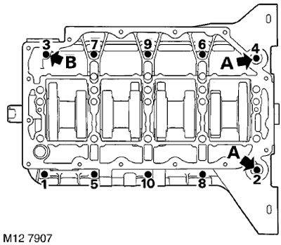
28. In the sequence shown in the figure, unscrew the 10 bolts securing the integral main bearing cap to the cylinder block and remove the cap.
NOTE: The 2 bolts 'A' shown in the illustration are located below the rear mount flange. Also note the position of bolt 'B' at the front of the bearing cap.
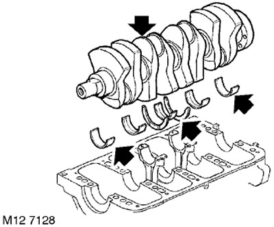
29. Remove the crankshaft from the cylinder block.
30. Remove 2 thrust half rings from the 3rd main bearing.
31. Remove the main bearing shells from the cylinder block and from the bearing cap.
Installation
1. Using solvent, clean the mating surfaces of the cylinder block and main bearing caps.
CAUTION: Do not use a metal scraper to clean mating surfaces.
2. Wipe the bearing beds in the cylinder block.
3. Wipe the bearing seats in the main bearing cap.
4. Wipe the connecting rod bearing beds in the connecting rods and in the connecting rod caps.
5. Clean the guide pins and holes for them.
6. Wipe the main and connecting rod journals of the crankshaft.
7. Wipe the crankshaft rear oil seal seat.
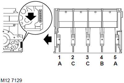
8. Copy the letter code of the main bearings from the bearing cap.
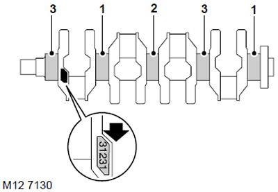
9. Copy the digital code of the main bearings from the front counterweight of the crankshaft.
10. Measure the diameter of the crankshaft main journals.
TECHNICAL SPECIFICATIONS, Engine - petrol K1.8.
11. Select main bearings for installation on the engine.
TECHNICAL SPECIFICATIONS, Engine - petrol K1.8.
12. The colored marks on the edge of the liner indicate their thickness: GREEN = thin liner, BLUE = medium thickness liner, RED = thick liner.
ATTENTION: If two different color-coded liners are to be installed on one journal, the thicker liner is installed in the main bearing cap. When installing the same crankshaft, the liners must be selected according to the table. Do not install liners of a thinner thickness.
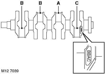
13. Write down the letter code of the crankpin size group located on the rear counterweight. The code designations are read from left to right, the first group refers to the 1st journal.
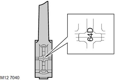
14. Write down the numbers of the size groups of the beds in the lower heads of the connecting rods. These are the numbers 5, 6 or 7, applied to the connecting rod caps. Select the corresponding liners.
TECHNICAL SPECIFICATIONS, Engine - petrol K1.8.
15. The color marks on the edge of the bearing indicate their thickness: YELLOW = thin bearing, BLUE = medium-thick bearing, RED = thick bearing. If bearings of two different color markings are to be installed on one journal, the thicker bearing is installed in the connecting rod cap.
16. Install the selected main bearings in the beds. Grooved bearings are installed in the cylinder block, flat bearings are placed in the main bearing cap.
17. Wipe and install new thrust half rings in the cylinder block, on the 3rd bed, with the oil grooves facing outward.
18. Lubricate the main journals with clean engine oil.
19. Holding the crankshaft so that the connecting rod journals are in a horizontal plane, place the crankshaft on the bed.
20. Check that the mating surfaces of the cylinder block and main bearing caps are clean and dry.
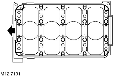
21. Apply a continuous bead of STC 4600 sealant to the cylinder block along the contours shown in the figure and spread it in a thin layer using a roller spatula.
ATTENTION: Assembly of prepared parts must be carried out immediately to prevent contamination of surfaces with applied sealant.
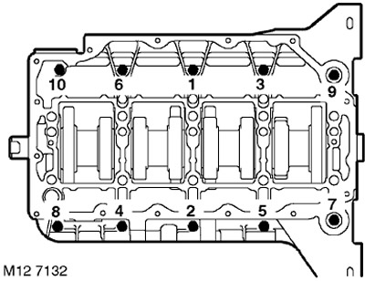
22. Lubricate the main journals with engine oil. Install the main bearing cap on the cylinder block, screw in the bolts, paying attention to the fact that the bolt with the flange head should be in position 10.
23. Tighten the bolts in the sequence shown in the figure:
- Stage 1: 5 Nm
- Stage 2: 30 Nm
24. Install the LRT-12-144 cylinder liner fasteners with the nylon nuts included in the fastener kit. The base of the cylinder liner fasteners should not protrude above the cylinder bore. Screw in the cylinder head fastening bolts until the cylinder liner fasteners are securely held.
CAUTION: The bolts used must be screwed into the same sockets in which they were located on the assembled engine.
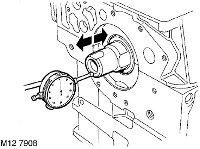
25. Install the indicator on the cylinder block, placing its leg on the end of the crankshaft nose.
26. Move the crankshaft back and set the indicator to zero.
27. Move the crankshaft forward and determine the axial displacement of the crankshaft.
28. Compare the obtained value with the requirements of the technical specifications.
TECHNICAL SPECIFICATIONS, Engine - petrol K1.8.
ATTENTION: If the axial movement (play) with new half rings installed exceeds the permissible value, the crankshaft must be replaced.
29. Remove the indicator.
30. Temporarily install the timing belt drive gear and the front crankshaft pulley, screw in the front pulley mounting bolt with a washer.
31. Install the selected connecting rod bearings into the connecting rod and into the caps.
32. Lubricate the connecting rod journals and connecting rod bearings with clean engine oil.
33. Carefully slide the connecting rods onto the journals, install the connecting rod caps, paying attention to the fact that the installation grooves in the cap and in the connecting rod body should be on different sides, tighten the connecting rod bolts with finger force.
34. Tighten the connecting rod cap mounting bolts:
- Stage 1: 20 Nm.
- Step 2: 45° turn.
NOTE: With the cylinder head removed and the main bolts tightened, the crankshaft will be difficult to turn.
35. Using a feeler gauge, measure the axial movement of the lower connecting rod head.
TECHNICAL SPECIFICATIONS, Engine - petrol K1.8.
36. Dampen a lint-free cloth with solvent and wipe clean the sealing surfaces of the main bearing cap and oil distributor cap.
37. Temporarily remove the cylinder liner fasteners LRT-12-144.
CAUTION: Do not rotate the crankshaft after removing the cylinder liner fasteners.
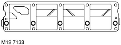
38. Apply a continuous bead of STC 4600 sealant along the contours shown in the figure and spread it in a thin layer using a roller trowel.
ATTENTION: Assembly of prepared parts must be carried out immediately to prevent contamination of surfaces with applied sealant.
39. Install the oil distributor cover onto the integral main bearing cover, fit the nuts and tighten them to 9 Nm.
ATTENTION: If the threaded portion of the cylinder head mounting bolts is damaged, a new oil distribution cover and a new oil receiver must be installed. The use of thread repair inserts (such as Helicoil) is not permitted.
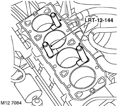
40. Install the LRT-12-144 fasteners onto the cylinder liners and lightly tighten the cylinder head fastening bolts.
CAUTION: The bolts used must be screwed into the same sockets in which they were located on the assembled engine.
41. Loosen the crankshaft pulley mounting bolt, remove the pulley and bolt with washer.
42. Wipe the oil pickup tube and mating surfaces.
43. Lubricate the new O-ring with clean engine oil and place it on the oil pickup tube.
44. Install the oil pickup pipe, screw in the bolts and tighten them to a torque of 10 Nm.
45. Replace the tray.
ENGINE - MODIFICATION K, volume 1.8, Piston group, Oil pan.
46. Wipe the dipstick tube and mating surfaces.
47. Install a new seal onto the dipstick housing.
48. Screw in the bolts securing the dipstick housing to the cylinder block and tighten them to a torque of 10 Nm.
49. Screw in the bolt securing the dipstick housing and thermostat housing to the cylinder block and tighten it to a torque of 10 Nm.
50. Insert the oil dipstick.
51. Install the oil pump.
ENGINE - MODIFICATION K, volume 1.8, Piston group, Oil pump overhaul.
52. Install the power steering pump bracket on the cylinder block, screw in the bolts and tighten them to a torque of 45 Nm.
53. Screw on the new oil filter and tighten it by hand until it makes full contact with the sealing surface, then tighten the filter another half turn.
54. Install the timing drive gear.
55. Install the rear crankshaft oil seal.
ENGINE - MODIFICATION K, volume 1.8, Piston group, Replacement of rear crankshaft oil seal.
56. Install the cylinder head.
ENGINE - MODIFICATION K, volume 1.8, Piston group, Cylinder head gasket.
Comments on this article