Contents: Dismantling ⇩ Installation ⇩
Dismantling
1. Remove the cylinder head.
ENGINE - MODIFICATION K, volume 1.8, Piston group, Cylinder head gasket.
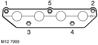
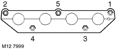
2. In the sequence shown in the figure, loosen and unscrew the 5 nuts securing the exhaust manifold to the cylinder head and remove the manifold.
3. Remove and discard the exhaust manifold gasket.
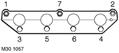
4. In the sequence shown in the figure, loosen and unscrew the 7 nuts securing the intake manifold to the cylinder head.
5. Remove the intake manifold and discard its gaskets.
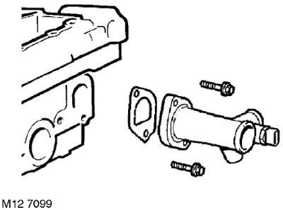
6. Unscrew the 2 bolts securing the outlet elbow pipe of the cooling system to the cylinder heads. Remove the pipe and dispose of the gasket.
7. Remove the spark plugs.
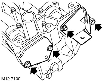
8. Unscrew the 4 bolts securing the front and rear camshaft oil seal covers and remove the covers.
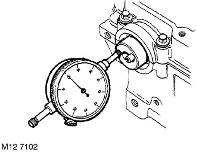
9. Check the axial play of the camshaft using a dial indicator.
TECHNICAL SPECIFICATIONS, Engine - petrol K1.8.
10. If the axial clearance exceeds the permissible value, install a new shaft (or new shafts) and check with them; if the clearance is still higher than the permissible value, replace the camshaft cover with the cylinder head assembly.
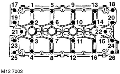
11. Gradually, in the sequence shown in the figure, loosen the 26 camshaft cover mounting bolts until the valve springs are completely unloaded.
12. Remove the camshaft cover.
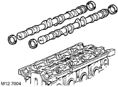
13. Mark the camshaft positions and remove the intake and exhaust camshafts. Remove the 4 oil seals from the shafts and discard the oil seals.
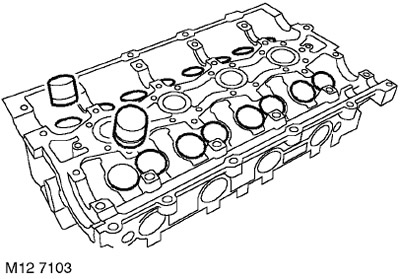
14. Using a magnet, remove the 16 hydraulic lifters from the cylinder head. The hydraulic lifters should be stored in the order in which they were installed and, at the same time, be in an inverted position so that oil does not leak out of them.
15. Check the compensators for wear, scoring and overheating.
16. Measure the diameter of each compensator. The measurement is made in the middle belt of the compensator.
TECHNICAL SPECIFICATIONS, Engine - petrol K1.8.
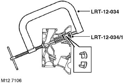
17. Using the LRT-12-034 valve spring compressor with the LRT-12-034/1 tip, compress the valve springs, remove the two valve spring crackers, release the spring and remove the LRT-12-034 valve spring compressor.

18. Remove the valve spring with the upper plate.
19. Remove the valve from the cylinder head.
20. Using the LRT-12-071 tool, remove and discard the valve stem seal.
21. Repeat the above with the remaining valves, laying out the valves with springs in the order in which they were installed on the cylinder head.
22. Place the cylinder head on the plane to which the intake manifold is attached and place wooden blocks underneath.
23. Perform the above operations with the exhaust valves.
24. Wipe the camshafts, the bearing surfaces of the camshaft journals in the bed, the mating surfaces of the camshaft bed and the cylinder heads.
25. Check the condition of the camshafts. If they are scratched, dented or excessively worn, replace the camshafts.
26. Place the camshafts in the cylinder head and apply a strip of deformable gauge to each of the journals.
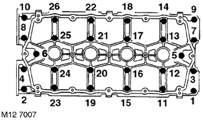
27. Install the camshaft cover and gradually tighten the bolts to 10 Nm in the sequence shown in the figure. DO NOT ROTATE the camshafts.
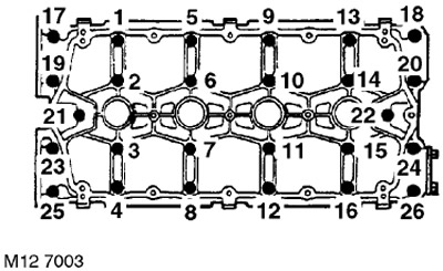
28. In the sequence shown in the figure, loosen and unscrew the camshaft cover mounting bolts.
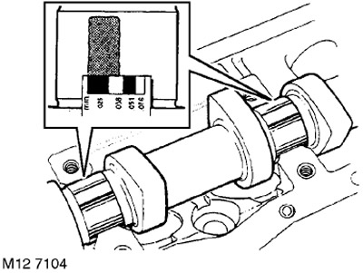
29. Measure the widest part of each gauge strip: Gap size = 0.060 - 0.094 mm. Maximum allowable gap = 0.15 mm.
30. If the clearance is greater than the permissible value, install new shafts and repeat the check. If the clearance is still too large, replace the cylinder head.
31. Using a rag soaked in oil, remove all traces of the deformed gauge from the necks.
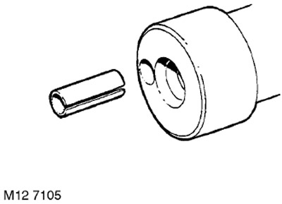
32. If you are installing an old shaft, remove the pin from it and install a new one, with the cut towards the shaft axis.
33. Wipe the camshaft gears, check the condition of the teeth and the pin holes for wear.
CAUTION: If gears manufactured by sintering (powder metallurgy technology) have been in contact with oil for a long time, they must be soaked in a solvent and then washed in clean solvent before installation.
34. Clean the mating surfaces of the integral camshaft cover and cylinder head. Wipe the surfaces under the intake and exhaust manifolds.
CAUTION: Do not use a metal scraper.
35. Clean the lower surface of the cylinder head from carbon deposits.
36. Blow out the oil passages and cooling system passages.
37. Check the cylinder head for damage, paying particular attention to the lower surface of the cylinder head.
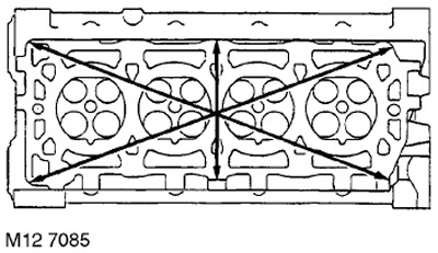
38. Check the cylinder head plane for warpage by placing a straight edge along the directions shown in the figure.
TECHNICAL SPECIFICATIONS, Engine - petrol K1.8.
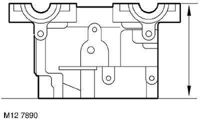
39. Check the cylinder head height.
TECHNICAL SPECIFICATIONS, Engine - petrol K1.8.
NOTE: Grinding the bottom surface of the cylinder head is permitted provided that the head height remains within acceptable limits.
40. Check the condition of the valve springs and measure the height of the springs in a free state.
TECHNICAL SPECIFICATIONS, Engine - petrol K1.8.
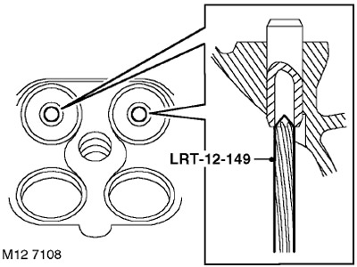
41. Using the LRT-12-149 tool, remove carbon deposits from the exhaust valve guide bushings.
ATTENTION: The device is inserted into the bushing from the lower plane of the cylinder head.
42. Remove carbon deposits from the intake valve guides, intake and exhaust valves, valve seats and the head fire surface. After completing the carbon removal procedure, blow out the head to remove all particles.
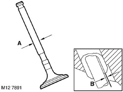
43. Measure and record the diameters 'A' of the stems of the old valves, replace the valve if the stem diameter is less than the permissible value.
TECHNICAL SPECIFICATIONS, Engine - petrol K1.8.
44. Using the procedure below, measure the clearances 'B' between the intake and exhaust valve stems and their guides.
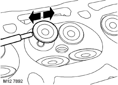
45. Insert the valve into the corresponding sleeve.
46. Move the valve plate up 10 mm and install the dial indicator as shown in the figure.
47. Move the valve disc toward the front of the cylinder head and set the indicator to zero, making sure that the indicator leg remains pressed against the disc.
48. Move the valve to the rear of the cylinder head and read the indicator 'B'
TECHNICAL SPECIFICATIONS, Engine - petrol K1.8.
49. Repeat this operation with each of the valves.
CAUTION: Store the cylinder head bolts in the order they were on the assembled engine.
50. Replace valves and valve guides if necessary.
TECHNICAL SPECIFICATIONS, Engine - petrol K1.8.
51. Place the cylinder head on wooden blocks.
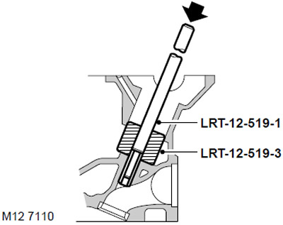
52. Insert the LRT-12-519-3 drift into the push rod socket and knock out the bushing using the LRT-12-519-1 drift.
NOTE: Lay out the valve guides in the order they were on the assembled engine.
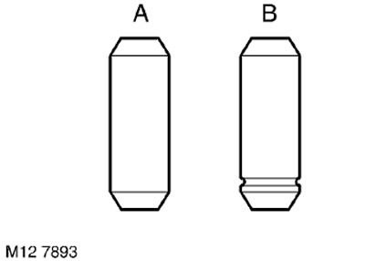
53. Determine the type of installed bushings: 'A' - Factory assembly 'B' - Replaced during operation.
CAUTION: Factory fitted 'A' bushings must be replaced with 'B' repair bushings.
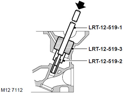
54. Install the valve guide into the guide socket with the groove facing the valve seat and install the LRT-12-519-2 limiter onto the guide.
NOTE: When replacing bushings, the cylinder head and bushing must be at room temperature.
55. Install the LRT-12-519-3 nylon mandrel into the compensator socket and drive the bushing with the LRT-12-519-1 mandrel until the limiter reaches the surface of the cylinder head.
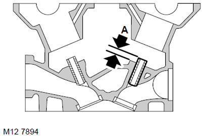
56. Measure the valve guide protrusion 'A': = 6.00 mm.
57. Check the condition of the valve seats and those valves that are intended to be reused.
58. Replace valve seats if necessary.
CAUTION: Use caution when removing seats to avoid damaging the seating surface.
59. Cool the new seats in liquid nitrogen and immediately install them into the cylinder head.
CAUTION: Do not heat the cylinder head. The seats after chamfering should not protrude above the lower plane of the cylinder head.
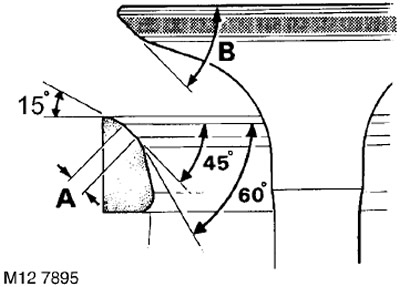
60. Cut the seat chamfers using a special cutter with a pilot, ensuring the following angles of inclination:
- 15°. - First cut
- 45° - Final cut with burr removal
- 60°. - Trimming to obtain the required chamfer width
61. Check the width of the valve chamfer and its angle:
- Chamfer width 'A' - Inlet = 1.2mm; Release = 1.6 mm
- Valve bevel angle 'B' - Inlet and Outlet = 45°.
62. Grind the valve faces using a fine-grained lapping paste.
63. Apply a thin layer of Prussian blue to the valve seat chamfer, insert the valve into the guide and press it down without turning. Remove the valve and check the uniformity and position of the fit using the imprint. The paint should be imprinted along the center line of the chamfer.
64. Grind and recheck the fit of the chamfer.
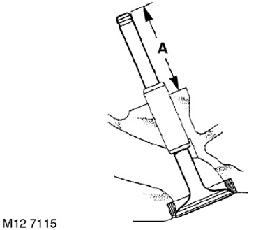
65. Check the protrusion of valve stem 'A'.
TECHNICAL SPECIFICATIONS, Engine - petrol K1.8.
66. If the valve stem protrudes more than the permissible limit, install a new valve and check the stem protrusion again. If this measure does not help, replace the valve seat.
Installation
1. Clean the intake and exhaust valves, spring retainers, crackers and valve springs.
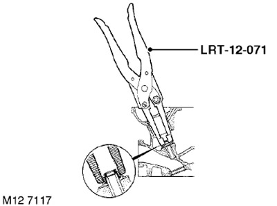
2. Lubricate the new valve stem seal with clean engine oil and install it onto the valve guide using the LRT-12-071 drift.
3. Lubricate the valve with clean engine oil and insert it into the guide.
The article was copied from a resource: www.LRman.ru
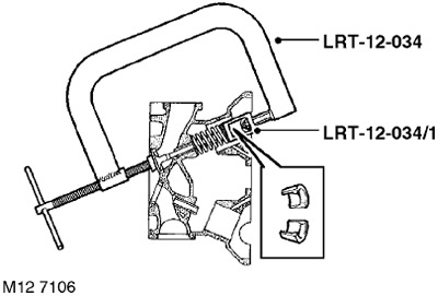
4. Install the spring with the plate, compress the spring with the LRT-12-034 valve spring compressor with the LRT-12-034/1 tip, install the crackers.
5. Repeat the procedure with the remaining valves.
6. Using a wooden block, strike the end of the valve stem two or three times so that the crackers take the working position in the grooves of the stem.
7. Lubricate the compensators with clean engine oil and insert them into their original places.
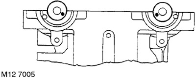
8. Lubricate the journals of the shafts, insert the camshafts and rotate them so that the installation pin under the toothed wheel of the intake shaft is at the "4 o'clock" position, and the exhaust shaft is at the "8 o'clock" position.
CAUTION: Do not reverse the intake and exhaust shafts.
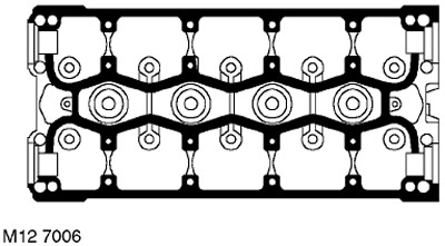
9. Apply continuous thin beads of STC 4600 sealant in the areas shown in the figure. Use a roller trowel to spread the sealant in a thin layer over the surface.
ATTENTION: Assembly of prepared parts must be carried out immediately to prevent contamination of surfaces with applied sealant.
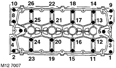
10. Install the camshaft cover and gradually tighten the bolts to a torque of 10 Nm in the sequence shown in the figure.
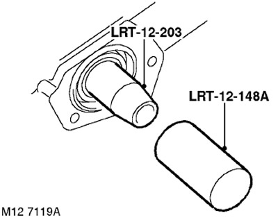
11. Remembering that the front seals are black and the rear seals are red, install new seals using the LRT-12-203 and LRT-12-148A drifts.
CAUTION: Seals must be installed dry. Do not use the LRT-12-148 driver to install seals.
12. Wipe the seal covers and mating surfaces.
13. Install the exhaust camshaft rear oil seal cover, screw in the bolts and tighten them to 25 Nm.
14. Install the intake camshaft rear oil seal cover, screw in the bolts and tighten them to 6 Nm.
15. Adjust the spark plug gap to 1.00 mm.
16. Screw in the spark plugs and tighten them to a torque of 27 Nm.
17. Install a new crankshaft gasket on the cylinder head, install the crankshaft and tighten the bolts to 9 Nm.
18. Clean the intake manifold and mating surfaces on the cylinder head.
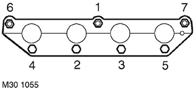
19. Install a new gasket on the head, a new intake manifold gasket, install the intake manifold, screw in the bolts and tighten them to 17 Nm.
20. Wipe the exhaust manifold and the mating surface on the cylinder head.
21. After installing the new gasket, install the exhaust manifold, tighten the nuts and tighten them to 45 Nm in the sequence shown in the figure.
22. Install the cylinder head.
ENGINE - MODIFICATION K, volume 1.8, Piston group, Cylinder head gasket.
Comments on this article