car logo Ford
car logo Volkswagen
car logo BMW
car logo Opel
car logo Audi
car logo Toyota
car logo Peugeot
English Русский
Български
Беларускі
Український
Српски
Hrvatski
Română
Polski
Slovenský
Magyar


Main
Freelander
Discovery
Range Rover
Defender
Contacts
Articles

Head cover — removal and installation (Defender 2007+)

 
  • Main
  • Defender
  • Defender 2007+
  • Power unit
  • Diesel engine ID4 2.4L
  • Head cover — removal and installation
 
        0  
Contents: Removal ⇩ Installation ⇩

Removal


Warnings:
  • Some fuel will inevitably spill during this operation. Make sure that all necessary precautions are taken to prevent fire and explosion.
  • Do not carry or use a cell phone while working with or in the immediate vicinity of any fuel related components. There is a risk of ignition of flammable vapors. Failure to follow these instructions may result in injury.
  • Do not smoke or carry a lighted cigarette or open flame of any type when working on or near fuel-related components. There is a risk of ignition of flammable vapors. Failure to follow these instructions may result in injury.
  • If fuel gets into your eyes, rinse them with cold water or a special eye wash solution and seek medical attention immediately.
  • Wash your hands thoroughly after handling fuel, as prolonged contact with the skin may cause irritation. If irritation occurs, seek medical attention.
  • Do not perform any repairs to the fuel system while the engine is running. Fuel pressure in the system can reach 2000 bar. Failure to follow this instruction may result in injury.


CAUTION: Diesel fuel injection equipment is manufactured to very precise tolerances and very small clearances. Therefore, absolute cleanliness is required when working on these components. Be sure to insert new plugs into all open ports and lines. Failure to do so may result in dirt entering the fuel injection system.


1. Disconnect the ground wire from the battery.

For more information, refer to the chapter: Disconnecting and connecting the battery (414-01 Battery, Battery Mounting and Cables, General Procedures).


2. Disconnect the positive crankcase ventilation (PCV) hose.
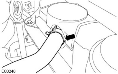
2. Disconnect the positive crankcase ventilation (PCV) hose.


3. Remove the fuel injectors.

For more information, refer to the chapter: Fuel Injector (303-04A Fuel Supply and Controls - ID4 2.4L Diesel Engine, Removal and Installation).

4. Release the fuel line.
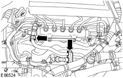
4. Release the fuel line.


5.
CAUTION: Plug all openings. Use new caps.


Disconnect the fuel return line.
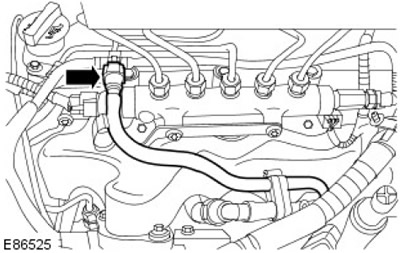
Disconnect the fuel return line.


6.
CAUTION: Plug all openings. Use new caps.


Disconnect the fuel return line.
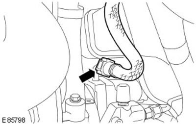
Disconnect the fuel return line.


7.
CAUTION: Plug all openings. Use new caps.


Remove the fuel return line.
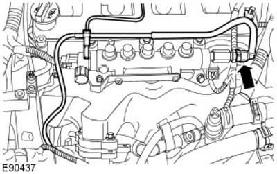
Remove the fuel return line.


8. Disconnect the engine wiring harness from the cylinder head cover.
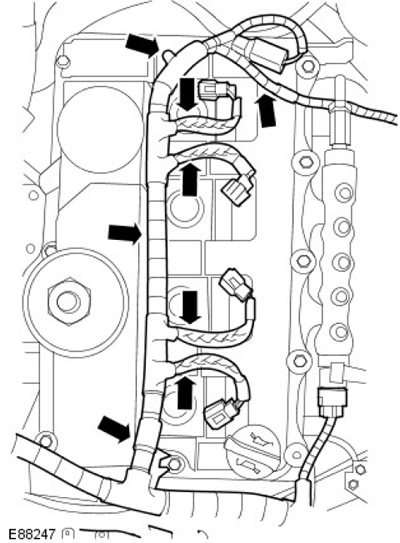
8. Disconnect the engine wiring harness from the cylinder head cover.


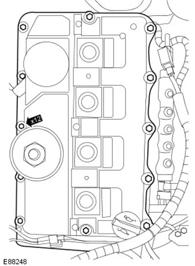
9. Remove the cylinder head cover.
  • Loosen the 12 bolts completely.
  • Remove the gasket and dispose of it.

Remove the gasket and dispose of it.


Installation


1.
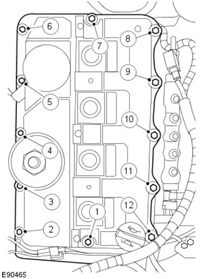
CAUTION: Tighten the bolts in the order shown in the illustration.


Install the elements back in place in reverse order.
  • Install a new gasket.
  • Tighten the bolts to 10 Nm.

Tighten the bolts to 10 Nm.


2. Connect the ground wire to the battery.

(The original text can be found at: lrman.ru)

For more information, refer to the chapter: Connecting the Battery (414-01 Battery, Battery Mounting and Cables, General Procedures).


This article is available at russian, bulgarian, belarusian, ukrainian, serbian, croatian, romanian, polish, slovak, hungarian
Article review: Saveliy Ushakov


Previous articles
Engine specifications
Engine diagnostics and checks
Draining and filling engine oil
Description and technical data
Cylinder block elements
Crankshaft and oil pan parts
Elements of the camshaft system
Cylinder head components

Current article
Head cover — removal and installation

Next articles
Gas distribution mechanism drive cover
Left engine mount — removal and installation
Oil pan — removal and installation
Oil pump — removal and installation
Flywheel — removal and installation
Oil cooler — removal and installation
Front Crankshaft Seal — Removal and Installation
Right engine mount — removal and installation


Similar articles from Land Rover repair manuals:
• Cylinder head and camshaft cover Freelander 2 (2006-2014)
• Left Cylinder Head Valve Cover Gasket: Up to 2003 Freelander 1 (1997-2006)
• Bridge cover bushing Discovery 3 (2004-2009)
• Left valve cover gasket Discovery 1 (1989-1998)
• Right cylinder head valve cover gasket Range Rover 3 (2001-2012)

Comments on this article


No comments yet


How much will 49 + 45 =


Defender 2007+ 
  • General information
  • Maintenance
  • Identification codes
  • Power unit
  • Diesel engine ID4 2.4L
  • Engine inspection
  • Engine cooling
  • Fuel supply
  • Fuel tank
  • Exhaust system
  • Accessory drive
  • Air filtration
  • Electronic parts
  • Mechanical gearbox
  • Transfer case
  • Clutch
  • Chassis
  • Car suspension
  • Wheels and tires
  • Steering
  • Steering column
  • Brake system
  • Front drive axle
  • Rear drive axle
  • Cardan shaft
  • Body and coating
  • Interior trim
  • Instrument panel and console
  • Exterior finish
  • Lockable body parts
  • Handles, locks, latches
  • Glass, frames and mechanisms
  • Windshield wipers and washers
  • Seats
  • Electrical equipment
  • Battery
  • Generator and regulator
  • Lighting and headlights
  • Winch
  • Heating and ventilation
  • Instrument panel
  • Other electronics


LRman.ru © 2013-2026 | Mobile version | Free Lander | Discovery | Range Rover | Defender | Contacts | | Sitemap |
Car repair and service instructions Land Rover: Freelander, Discovery, Range Rover, Defender
We use cookies to make pages load faster and provide a more user-friendly experience 🍪