Contents: Removal ⇩ Installation ⇩
Special tool(s)
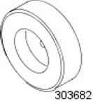 | Timing Belt Cover Installation Tool 303-682 |
Removal
1.
WARNING: Never work on a vehicle supported only by a jack. Always support the vehicle with special stands.
Raise and support the vehicle.
2. Disconnect the ground wire from the battery.
For more information, refer to the chapter: Disconnecting and connecting the battery (414-01 Battery, Battery Mounting and Cables, General Procedures).
3. Drain the cooling system.
For more information, refer to the chapter: Draining/filling coolant and bleeding air from the cooling system (303-03 Engine Cooling - ID4 2.4L Diesel Engine, General Procedures).
4. Remove the accessory drive element bracket.
For more information, refer to the chapter: Belt/Accessory Chain Tensioner Bracket (303-05 Accessory Drive - ID4 2.4L Diesel Engine, Removal and Installation).
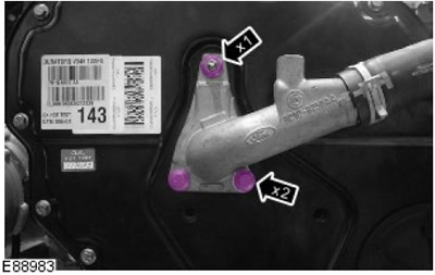
5. Install the elbow pipe of the cylinder head cooling system.
- Remove the nut.
- Remove two bolts.
- Remove the sealing ring and dispose of it.
6. Remove the front crankshaft seal.
For more information, refer to the chapter: Front Crankshaft Seal (303-01 Engine - Diesel engine ID4 2.4L, On-car repair).
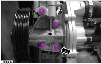
7. Reposition the coolant hose.
- Remove 4 bolts.
- Remove the gasket and dispose of it.
8. Using a suitable tool, remove and discard the timing belt cover.
- Remove 20 bolts.
- Unscrew 2 nuts.
Installation
1. Clean the mating surfaces of the engine timing cover.
2.
Warnings:
- Install a new timing cover. Failure to do so may result in damage to the vehicle.
- Install the engine timing cover within five minutes of applying the sealant. Failure to do so may result in damage to the vehicle.
NOTE: There may be some differences from what is shown in the pictures, but the basic information is correct.
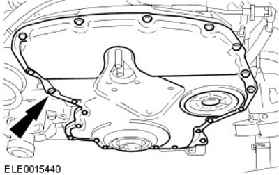
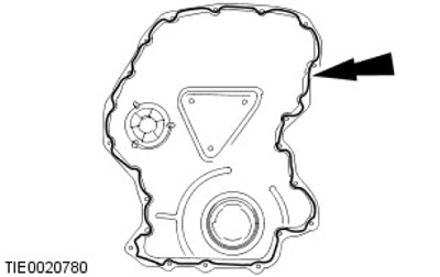
Apply a 3mm bead of sealant to the four tees.

3. Apply a 3mm bead of sealant to the engine timing cover.
4.
CAUTION: Make sure the engine timing cover does not come into contact with the engine until the correct position is reached.
With the help of a second mechanic, install the engine timing cover.
5.
NOTE: Engine shown removed for clarity.
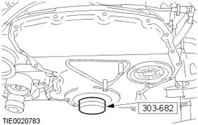
Using a special tool, adjust the position of the engine timing cover.
- Screw in and tighten the 2 engine timing cover bolts to 6 Nm.
- Install and tighten the remaining 16 engine timing cover bolts and install and tighten the 2 nuts to 6 Nm.
- Loosen the engine timing cover bolts and nuts 360 degrees.
- Install the special tool.
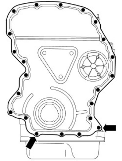
6. Tighten the engine timing cover nuts and bolts.
- Tighten the engine timing cover nuts and bolts to 3 Nm.
- Tighten the engine timing cover nuts and bolts in the following sequence:
- Tighten the 2 indicated bolts to 11 Nm.
- Tighten the remaining nuts and bolts to 10 Nm.
7.
NOTE: Clean the contact surfaces of the parts.
Secure the coolant pump.
- Install a new gasket.
- Tighten the bolts (tightening torque 22 Nm).
8.
NOTE: Clean the contact surfaces of the parts.
Install the elbow coolant pipe onto the cylinder head.
- Install a new O-ring.
- Tighten the nut (tightening torque 22 Nm).
- Tighten the bolts (tightening torque 22 Nm).
9. Install the accessory drive component bracket.
For more information, refer to the chapter: Belt/Accessory Chain Tensioner Bracket (303-05 Accessory Drive - ID4 2.4L Diesel Engine, Removal and Installation).
10. Connect the ground wire to the battery.
For more information, refer to the chapter: Connecting the Battery (414-01 Battery, Battery Mounting and Cables, General Procedures).
11. Fill the cooling system with coolant and bleed air from the system.
For more information, refer to the chapter: Draining/filling coolant and bleeding air from the cooling system (303-03 Engine Cooling - ID4 2.4L Diesel Engine, General Procedures).
Comments on this article