Contents: Removal ⇩ Installation ⇩
Before disconnecting the battery, make sure that all precautions specified for this procedure have been followed.
GENERAL INFORMATION, Precautions when working with electrical equipment.
Removal
1. Disconnect the negative cable from the battery.
2. Remove the cylinder head gasket.
TD6 ENGINE, REPAIR WORK, Cylinder head gasket.
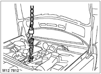
3. Install the rigging bracket on the cylinder block and secure it with a bolt.
4. Place the lifting chain on the bracket and completely lift the engine.
5. Remove the oil pump.
ENGINE TD6, REPAIR WORK, Oil pump.
6. Remove the front crankshaft oil seal.
TD6 ENGINE, REPAIR WORK, Replacing the front crankshaft oil seal.
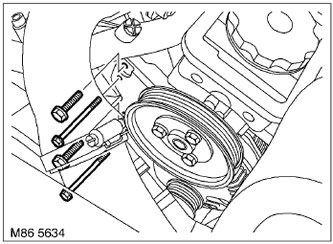
7. Unscrew the 4 bolts securing the power steering pump, move the pump away and secure it.
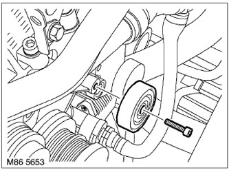
8. Loosen the bolt securing the upper idle pulley of the accessory drive belt and remove the pulley.
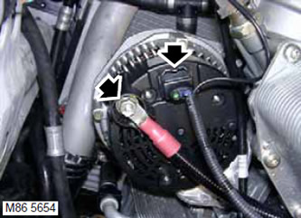
9. Unscrew the nut securing the wire going from the battery to the generator and move the wire to the side.
10. Disconnect the connector from the generator.
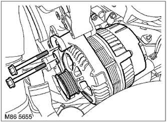
11. Unscrew the 2 bolts securing the generator to the bracket, fasten it to the idle pulley bracket and remove the generator.
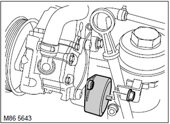
12. Loosen the nut securing the accessory drive belt tensioner and remove the tensioner.
13. Remove and discard the tensioner lever seal.
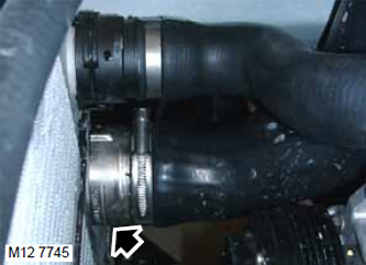
14. Loosen the clamp and disconnect the air hose from the air intercooler.
CAUTION: To prevent contamination, install plugs on open connectors.
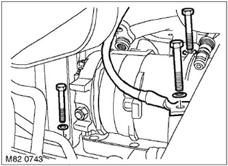
15. Unscrew the 3 bolts securing the air conditioning compressor, move the compressor to the side and secure it.
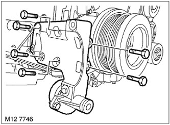
16. Unscrew the 6 bolts securing the air conditioning compressor bracket and remove the bracket.
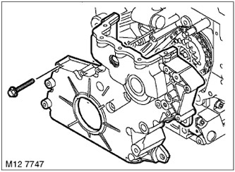
17. Unscrew 14 bolts, move the cover away from the block and remove it. Unscrewing the bolts releases the drive belt tensioner for the attachments.
18. Remove the camshaft drive chain from the fuel pump sprocket.
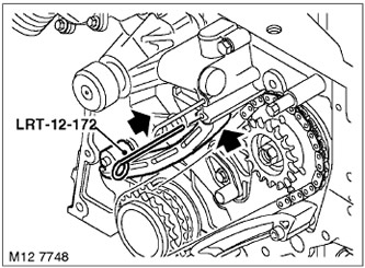
19. Push the lower chain tensioner plunger fully into the tensioner housing to secure it with stud LRT-12-172.
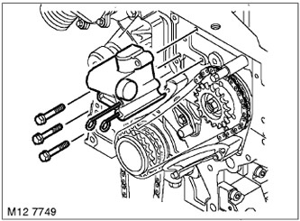
20. Unscrew 3 bolts and remove the timing chain tensioner.
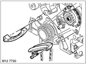
21. Remove the upper fuel pump drive chain guide.
22. Loosen the bolt and remove the lower fuel pump drive chain guide. Discard the bolt.
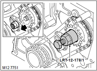
23. Holding the fuel pump drive sprocket, unscrew its mounting nut.
24. Install the LRT-12-178/1 puller on the fuel pump sprocket and, tightening the central bolt of the puller, remove the sprocket.
25. Remove the LRT-12-178/1 puller from the sprocket.
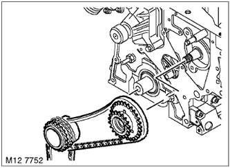
26. Remove the sprockets and chains from the crankshaft and from the fuel pump.

27. Unscrew the bolt and remove the oil nozzle designed to lubricate the chain.
28. Using a sharp blade, separate the timing cover gasket and remove it.
Installation
1. Wipe the timing cover and mating surface, pins and pin seats.
2. Using a blade, separate and remove the coolant pump gasket, then install a new timing cover gasket.
3. Wipe the oil nozzle and the corresponding mating surface.
4. Install the oil nozzle in place and tighten the mounting bolt. Tightening torque 10 Nm.
5. Wipe the crankshaft sprockets, fuel pump and their installation locations.
6. Wipe the oil and fuel pump drive chains.
7. Lubricate the chains and sprockets.
8. Place the oil and fuel pump drive chains onto the crankshaft and fuel pump sprockets.
9. Place the sprockets with chains on the crankshaft and on the fuel pump.
10. Screw on the fuel pump sprocket mounting nut and tighten it. Tightening torque 65 N·m.
The article was copied from this resource: lrman.ru
11. Wipe the fuel pump drive chain guides.
12. Place the lower fuel pump drive chain guide onto the mounting pin and secure it with a new bolt. Tightening torque 24 N·m.
13. Install the upper fuel pump drive chain guide.
14. Wipe the timing chain tensioner and mating surface. Make sure the oil feed channel is clean.
15. Install the tensioner in place and tighten the mounting bolts. Tightening torque 10 Nm.
16. Press the tensioner plunger to remove stud LRT-12-172 and seat the plunger against the tensioner shoe.
17. Wipe the camshaft drive chain.
18. Lubricate the camshaft drive chain.
19. Install the camshaft drive chain to the fuel pump sprocket.
20. Wipe the timing cover.
21. Install the timing cover onto the cylinder block.
22. To ensure the correct position of the accessory drive belt tensioner, temporarily install the tensioner lever.
23. Tighten the timing cover mounting bolts evenly and consistently. Tightening torque 15 N·m.
24. Remove the accessory drive belt tensioner lever.
25. Install the seal on the belt tensioner lever bushing.
26. Install the tensioner lever in place and tighten the mounting bolts. Tightening torque 10 Nm.
27. Wipe the air conditioning compressor bracket and mating surface.
28. Install the compressor bracket in place and tighten the mounting bolts. Tightening torque 25 Nm.
29. Wipe the compressor and mating surface, locating pins and pin seats.
30. Install the compressor in place, put on the ground wire and tighten the mounting bolts. Tightening torque 25 Nm.
31. Wipe the intercooler air hose and mating surface.
32. Place the hose onto the air-to-air intercooler radiator and secure it with a clamp.
33. Wipe the generator and mating surface.
34. Wipe the idler roller bracket and mating surface.
35. Install the generator and idler roller bracket, tighten the bolts. Tightening torque 45 N·m.
36. Connect the positive wire to the generator, screw on the nut and tighten it. Tightening torque 13 N·m.
37. Connect the connector to the generator.
38. Wipe the upper idler roller of the accessory drive belt and the mating surface.
39. Install the roller in place and tighten the mounting bolt. Tightening torque 25 Nm.
40. Wipe the power steering pump and mating surfaces.
41. Install the power steering pump on the bracket and screw in the mounting bolts. Tighten the M8 bolts to 25 N·m and the M6 bolts to 10 N·m.
42. Install the front crankshaft oil seal.
TD6 ENGINE, REPAIR WORK, Replacing the front crankshaft oil seal.
43. Install the oil pump.
ENGINE TD6, REPAIR WORK, Oil pump.
44. Unhook the rigging chains.
45. Loosen the rigging eye mounting bolt and remove the eye.
46. Install the cylinder head gasket.
TD6 ENGINE, REPAIR WORK, Cylinder head gasket.
47. Connect the negative cable to the battery.
Comments on this article