Removal
1. Remove the cylinder head gasket.
TD6 ENGINE, ENGINE OVERHAUL, Cylinder Head Gasket.
2. Remove the connecting rod bearings.
TD6 ENGINE, ENGINE OVERHAUL, Replacing connecting rod bearings.
Disassembly
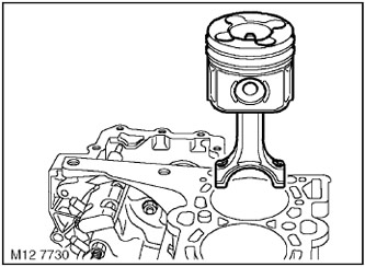
1. Remove carbon deposits from the top of the cylinder.
2. Carefully knock the piston out of the cylinder.
CAUTION: When knocking out the piston, make sure that the connecting rod does not touch the cylinder bore and oil jets. (if any are installed)
3. Knock out the remaining 5 pistons.
4. Clamp the connecting rod in a vice with soft jaws.
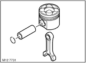
5. Carefully remove and discard the 2 piston pin retaining rings.
6. Push the piston pin out of the piston and connecting rod and remove the piston.
Examination
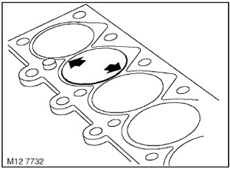
1. Pistons and cylinders: Measure the cylinder diameter at the lower, middle and upper belts in the plane shown in the figure.
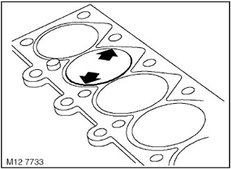
2. Record the measurement results. Repeat the measurement in the plane shown in the figure and, using two groups of measurements, calculate the ovality and taper of the cylinder.
TECHNICAL SPECIFICATIONS, Engine - Td6.
3. Starting with piston No.1, measure the skirt diameter in the plane perpendicular to the piston pin axis, at a distance of 12 mm from the lower edge of the skirt:
4. Compare the piston diameter with the cylinder diameter and calculate the gap between the piston and the cylinder.
TECHNICAL SPECIFICATIONS, Engine - Td6.
5. Remove the compression rings, composite oil control rings and oil control ring expander from the new piston.
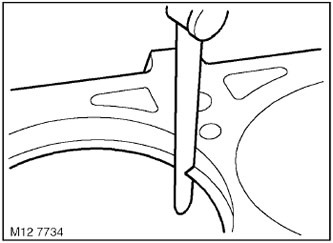
6. Insert new rings into the cylinder and check the mounting clearance in them at a distance of 30 mm from the upper plane of the block. When measuring the clearance, make sure that the rings are in a plane perpendicular to the cylinder axis.
TECHNICAL SPECIFICATIONS, Engine - Td6.
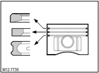
7. Put on the oil scraper rings and ring expander, make sure that the rings in the lock are flush and do not overlap.
8. Place the second compression ring with the 'TOP' mark facing up.
9. Place the top compression ring with the 'TOP' mark facing up.
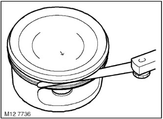
10. Check the clearance between the ring and the piston groove.
TECHNICAL SPECIFICATIONS, Engine - Td6.
11. Check the fit of the piston pin in the piston: the pin should move with little effort, without jamming or noticeable play.
12. Check the wear of the connecting rod upper head bushing, check the fit of the pin in the bushing: the pin should move with little effort, without jamming or noticeable play. The connecting rod upper head bushings are not replaceable. If necessary, replace the connecting rod assembly.
13. Check that the connecting rod is not deformed. Install a new bearing with a running-in layer, marked BLUE, into the connecting rod. Install a new bearing, marked RED, into the connecting rod lower head cap.
14. Install the caps on the connecting rods, screw the old bolts back into place and tighten them to a torque of 5 N·m.
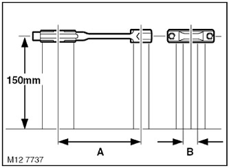
15. Check the geometry of the connecting rods (no deformation), determining the size of A and B, as shown in the figure.
TECHNICAL SPECIFICATIONS, Engine - Td6.
16. Check that there is no deformation on either side of the connecting rod.
17. After checking the parallelism of the heads, unscrew the connecting rod cap mounting bolts and lay them out in the order of installation.
Assembly
1. Wipe the cylinder bore, pistons, piston rings and connecting rods.
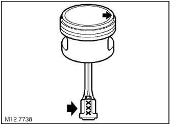
2. Place the pistons on your connecting rods, making sure the number on the small end of the connecting rod is aligned with the arrow on the piston crown as shown in the picture.
3. Lubricate the piston pins, piston bores and connecting rod upper heads with engine oil. Insert the piston pins and secure them with new retaining rings, which must be fully seated in their grooves.
4. Lubricate the pistons, piston rings and cylinder bore with clean engine oil.
5. Check the freedom of movement of the rings in their grooves. Spread the ring locks 120° relative to each other so that the locks are not on the most loaded side of the piston. (left side of the piston when looking at its front).

6. Compress the piston rings with a special tool.
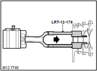
7. Install the LRT-12-176 guides onto the connecting rod to protect the cylinder bore and crankpin.
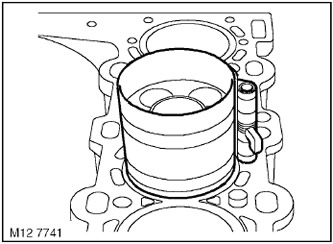
8. Insert the piston into the cylinder so that the arrow on the bottom of the piston points towards the front of the engine.
9. Remove the LRT-12-176 guides from the connecting rods.
Repair
1. Install the connecting rod bearings.
TD6 ENGINE, ENGINE OVERHAUL, Replacing connecting rod bearings.
2. Check the piston protrusion.
TD6 ENGINE, ENGINE OVERHAUL, Checking piston protrusion with cylinder head removed.
(The original was published on the portal: www.LRman.ru)
3. Install the cylinder head gasket.
TD6 ENGINE, ENGINE OVERHAUL, Cylinder Head Gasket.
Comments on this article