Dismantling
1. Place the vehicle on a two post lift.
2. Disconnect "negative" battery terminal.
3. Fix a cowl in vertical position.
4. Drain the engine coolant.
COOLING SYSTEM: Td4 engine, ADJUSTMENTS, Coolant drain, system flush and fill.
5. Remove air hoses of inlet system.
6. Remove the battery pad.
SYSTEM OF STARTING THE ENGINE AND CHARGING THE BATTERY, REPAIR WORKS, Support tray - storage battery.
7. Remove the engine control unit (ECM).
ENGINE CONTROL SYSTEM: EDC, REPAIR WORK, Engine control unit (ECM).
8. Disconnect the connector from the glow plug control unit.
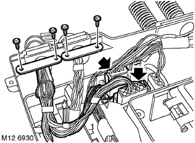
9. Disconnect the multi-position connector of the motor harness of the control system from the mounting box.
10. Disconnect the clamps of the engine harness of the control system.
11. Disconnect the engine harness from the junction box and lay it on top of the engine.
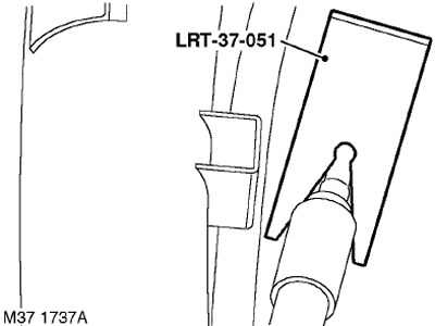
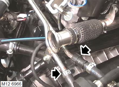
12. Using tool LRT-37-051, disconnect and disconnect the clutch actuator tube.
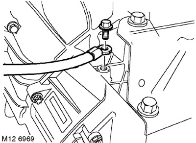
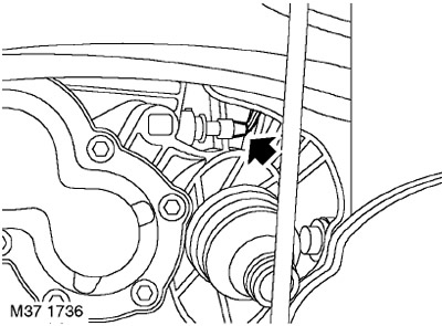
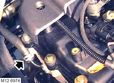
13. Turn out a bolt and disconnect the tire "masses" from the gearbox.
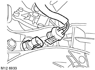
14. Disconnect a socket from the contact gauge of inclusion of the first transfer.
15. Disconnect the connector from the reversing light switch.
16. Remove the cap from the pole piece and disconnect the two wires from the starter retractor.
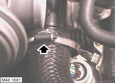
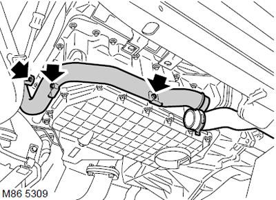
17. Loosen the clamp and disconnect the air hose leading to the intercooler from the engine.
CAUTION: Before disconnecting or removing system components, make sure that the surfaces adjacent to the connection points are free of dirt. Install plugs in fittings and piping to keep dirt out of the system.
18. Prepare containers to collect residual fuel.
19. Turn away collars and disconnect fuel hoses from a fuel stage.
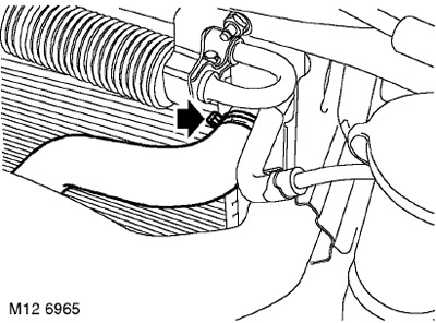
20. Loosen the clamp and disconnect the top hose from the radiator.
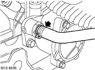
21. Turn away a collar and disconnect a hose of heating system from a distributive tube of system of cooling.
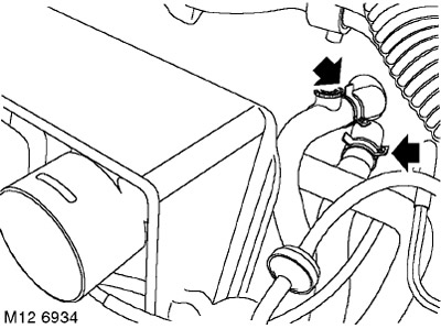
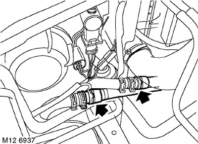
22. Loosen the clamps and disconnect the hoses from the heater.
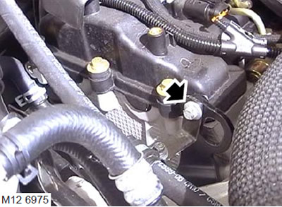
23. Turn away a bolt of fastening of a collar of a tube of the hydraulic booster to an eye.
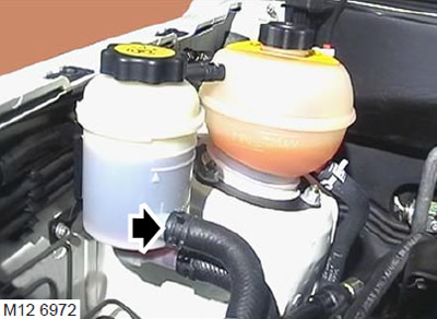
24. Place a container under the power steering reservoir, loosen the clamp and remove the hose from the reservoir. Let the working fluid drain.
CAUTION: Do not allow oil or liquid to come into contact with the generator.
25. Cover the generator so that it does not get working fluid.
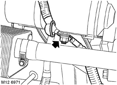
26. Loosen the clamp and disconnect the vacuum hose from the vacuum pump.
27. Mark the location of the vacuum tubes and remove both vacuum tubes from the reservoir.
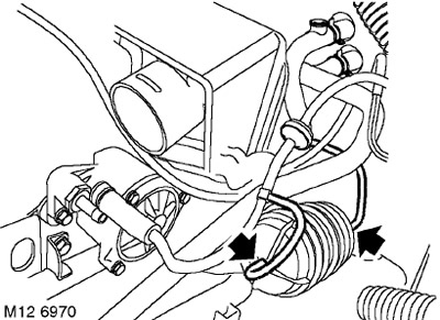
28. Loosen the clamps and remove the inlet and outlet hoses from the flare heater (FBH).
29. Remove a back cross beam.
FRONT SUSPENSION, REPAIR WORKS, Front subframe.
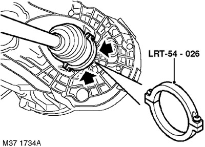
30. Install tool LRT-54-026 on the drive shaft inner joint. Using the lever, release the drive shafts from the transfer case and gearbox.
31. With the help of a partner, move the hubs outward and remove the drive shafts from the transfer case and from the gearbox.
32. Remove a reception pipe of system of release.
MANIFOLDS AND EXHAUST SYSTEM - Td4, REPAIR WORK, Downpipe.
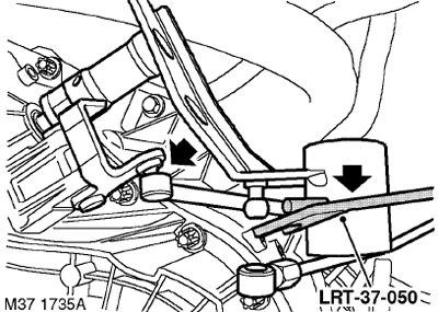
33. Using tool LRT-37-050, disconnect the gear selection rod from the gear selection rod.
34. Raise one rear wheel so that the driveshaft can be rotated to gain access to the bolts.
35. To facilitate subsequent assembly, mark the position of the viscous coupling in relation to the transfer case flange.
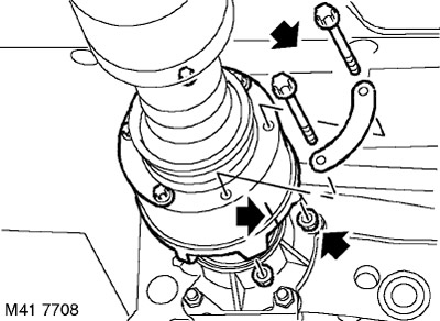
36. Turn away 6 nuts and remove bolts of fastening of the cardan shaft to a leading flange of a distributing box.
37. Remove the propeller shaft from the transfer box drive flange and tie it aside.
CAUTION: Care must be taken when removing the three-roller joint from the transfer case. In order not to damage the cover, it must not be fully stretched, the hinge body must be protected from shock.
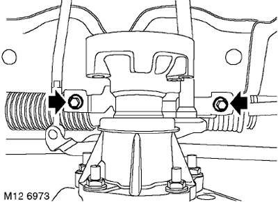
38. Remove the two bolts that secure the shift rods to the bulkhead and secure the rods to the side.
39. Drain the gearbox oil.
MANUAL GEARBOX - GETRAG, ADJUSTMENT, Transmission oil change in the box.
40. Drain the oil from the transfer case.
TRANSFER BOX, ADJUSTMENTS, Changing the transmission oil in the transfer case: except for the North American market.
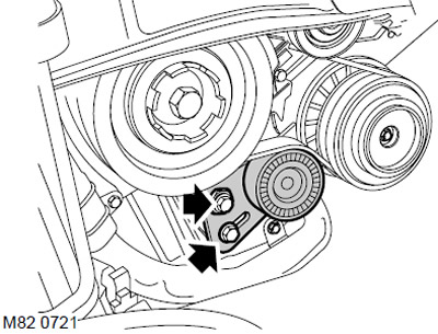
41. Models with air conditioning system: Loosen the axle and bolt of the A/C compressor belt tensioner.
42. Models with A/C system: Remove the belt from the compressor pulley.
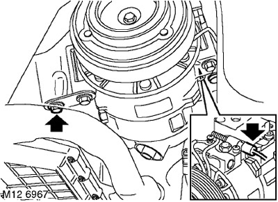
43. Models with A/C system: Loosen the bolt securing the compressor bracket to the sump, but do not remove it.
44. Models with air conditioning system: Remove the three bolts securing the distribution tube to the sump and to the cylinder block.
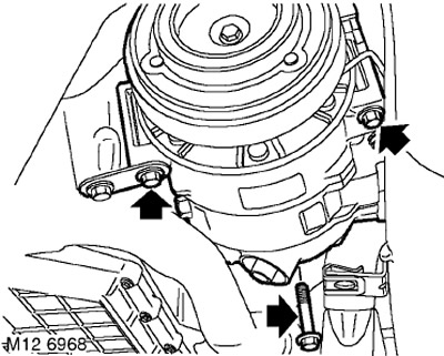
45. Models with air conditioning system: Remove the 3 bolts securing the air conditioning compressor to the bracket, move the compressor to the side and fix it.
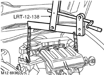
46. Install the LRT-12-138 traverse onto the lifting chains and hook them onto the engine lifting eyes.
47. Remove the hydraulic support.
ENGINE - Td4, Intake and exhaust camshafts, Right engine hydraulic mount.
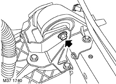
48. Turn out a through bolt of fastening of the left support of the engine to a transmission.
49. Lower the engine with the gearbox to the floor.
Make sure that the turbocharger hose does not cling to the shift rods located on the bulkhead.
50. Lower the chains, unhook and remove the LRT-12-138 yoke.
Installation
1. Attach the LRT-12-138 adjustable head hoist to the motor.
2. Install the silent blocks on the support.
3. Raise the engine with the gearbox, move the gearbox bracket to the installation site.
4. Pass the through bolt of the gearbox bracket into the support on the body and tighten the bolt to 100 Nm.
5. Install the hydraulic support.
ENGINE - Td4, Intake and exhaust camshafts, Right engine hydraulic mount.
6. Lower the chains, unhook and remove the LRT-12-138 yoke.
7. Establish a reception pipe of system of release.
MANIFOLDS AND EXHAUST SYSTEM - Td4, REPAIR WORK, Downpipe.
8. Place the gear shift rods on the bulkhead, screw in the mounting bolts and tighten them to a torque of 25 Nm.
9. Attach the top and bottom links to the gear selector lever.
10. Install the cardan shaft on the transfer case drive flange so that the previously made marks line up. Tighten nuts and bolts to 40 Nm.
11. Reinstall the rear beam.
FRONT SUSPENSION, REPAIR WORKS, Front subframe.
12. Wipe the ends of the drive shaft and the places of its installation in the hub and in the differential.
13. With the help of a partner, insert the shafts into the gearbox, holding them at the right angle so as not to damage the gearbox oil seals.
14. Models with air conditioning system: Install the compressor in place and tighten the mounting bolts. Tightening torque 25 Nm.
15. Models with air conditioning system: Install the compressor bracket on the pallet, screw in the bolts and tighten them to a torque of 10 Nm.
16. Models with air conditioning system: Install the cooling system distribution pipe on the sump, screw in the bolts and tighten them. Tightening torque 10 Nm.
17. Air Conditioning Models: Check that the compressor drive belt, compressor pulley, crankshaft pulley and rollers are clean.
18. Models with air conditioning system: Install the belt on the compressor pulley.
19. Models with air conditioning system: Tension the compressor drive belt.
AIR CONDITIONING SYSTEM, Air conditioning compressor drive belt - for models with Td4 engine, Air conditioning compressor drive belt - for models with Td4 engine.
20. Connect the cooling system hoses to the flare heater and secure with clamps.
21. Wipe the hoses and fittings of the vacuum reservoir.
22. Attach vacuum hoses to a vacuum receiver.
23. Wipe the hoses and vacuum pump fittings.
24. Attach vacuum hoses and tighten collars.
25. Wipe the hoses and fittings of the hydraulic booster reservoir.
26. Put the hoses on the fitting of the hydraulic booster reservoir and tighten the clamps.
27. Tighten the bolt securing the hydraulic booster tube to the eye to 10 Nm.
28. Attach the heater hoses and secure them with a clamp.
29. Attach a hose of system of cooling to a distributive tube and fix it with a collar.
30. Connect the top hose to the radiator and secure with a clamp.
31. Attach the fuel pipes to the clamps on the fuel rail.
32. Put a hose on a radiator of an intercooler of air and fix it with a collar.
33. Connect the battery cable to the starter retractor and tighten the nut to 13 Nm.
34. Connect the connector to the first gear engagement switch.
35. Connect the reversing light switch connector.
36. Attach the clutch tube quick connector.
37. Put a wire on the gearbox "masses" and tighten the mounting bolt. Tightening torque 25 Nm.
38. Route the wire harnesses to the junction box and install the grommets.
39. Secure the wire harnesses with clamps and screws.
40. Connect the connectors.
41. Install the engine control unit (ECM).
ENGINE CONTROL SYSTEM: EDC, REPAIR WORK, Engine control unit (ECM).
42. Fill the gearbox with oil.
MANUAL GEARBOX - GETRAG, ADJUSTMENT, Transmission oil change in the box.
43. Untie the hood and close it.
44. Replace the battery tray.
SYSTEM OF STARTING THE ENGINE AND CHARGING THE BATTERY, REPAIR WORKS, Support tray - storage battery.
45. Install intake hoses.
46. Fill the engine with coolant.
COOLING SYSTEM: Td4 engine, ADJUSTMENTS, Coolant drain, system flush and fill.
Comments on this article