Contents: Removal ⇩ Installation ⇩
Special tool
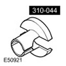 Fuel System Spring Lock Release Tool 310-044
 |
Removal
NOTE: Removing the intake manifold on early models requires partial removal of the fuel rail and removal of the purge valve and support bracket. Some excess material must also be removed from the intake manifold after removal.; see steps 1 and 2 of the installation procedure.
1. Disconnect the ground cable from the battery. For more information, refer to Specification
2. Secure the hood in the service position. Release the hood struts.
3. Remove the engine cover. For more information, refer to Engine Cover - 4.0L (12.30.50)
4. Remove the air intake resonator. For more information, refer to Air Intake Resonator (19.70.03)
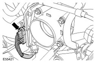
5. Disconnect the throttle body electrical connector.
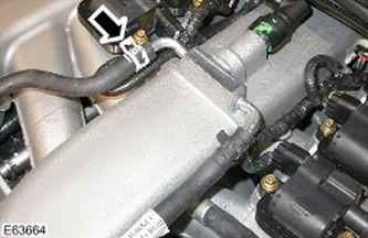
6. Disconnect the intake manifold coolant hose.
- To minimize coolant loss, pinch the appropriate hose.
- Release the clamp.
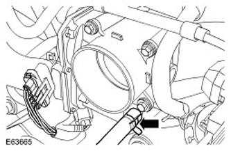
7. Disconnect the throttle body coolant hose.
- To minimize coolant loss, pinch the hose.
- Release the clamp.
8.
CAUTION: Before disconnecting or disassembling parts, ensure that the area around the mating surfaces and connections is free of contamination. To avoid contamination of the system, close all open connections.
Disconnect the engine crankcase ventilation hose.
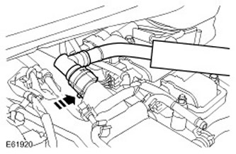
9. Disconnect the right engine crankcase ventilation hose.
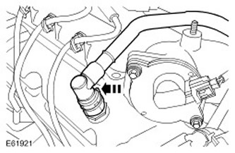
10. Disconnect the EGR valve electrical connector.
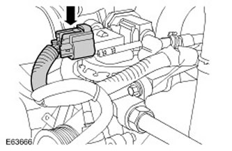
11. Disconnect the EGR valve feed line.
- Loosen the union nut of the EGR valve feed line on the exhaust manifold.
- Remove the union nut securing the EGR line to the valve.
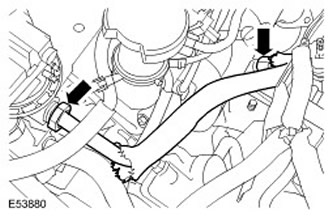
12. Disconnect the intake manifold vacuum pipe assembly.
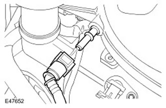
13. Disconnect the intake manifold adjusting valve electrical connector.
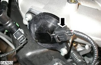
14. Secure the purge line to the intake manifold.
- Remove the clamp mounting bolt.
- Select a spacer sleeve.
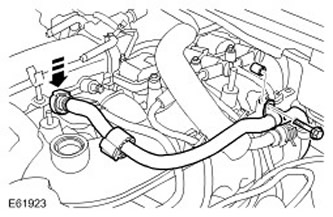
15. Release the coil wiring harness.
- Release the 6 clamps.
- Unscrew the 2 coil harness ground nuts.
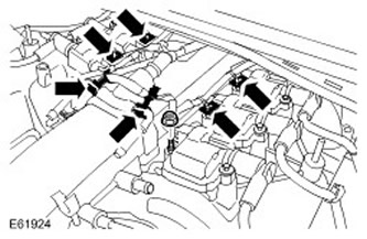
16. Disconnect the 6 coil electrical connectors.
17.
NOTE: Mark the installation positions of the fasteners.
Remove the 2 rear ignition coils.
- Disconnect the spark plug wires from the coils.
- Remove 2 bolts and 2 studs.
- Discard the retainer O-rings to facilitate subsequent installation.
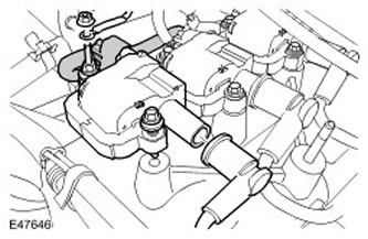
18. Disconnect the high tension wires from the ignition coils. Move the wires to the side.
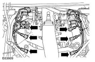
19. Move the engine wiring harness to the side to provide access.
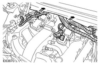
20. Remove the 8 intake manifold bolts.
21.
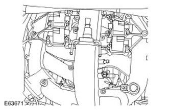
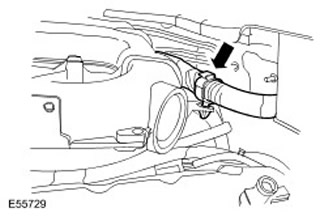
NOTE: The clamp type may vary depending on the steering position. Release the intake manifold wiring harness clamp.
22.
WARNING: The vehicle must be kept in a well-ventilated, closed area. Signs "No smoking! Gasoline vapors!" must be posted around the vehicle.
CAUTION: Some fuel will inevitably spill during this operation. Take all necessary measures to prevent fire and explosion.
CAUTION: Wait at least 30 seconds after stopping the engine before attempting any repairs to the high pressure fuel injection system. Failure to do so could result in personal injury.
WARNING: If fuel gets into your eyes, rinse with cold water or an eye wash solution and seek medical attention immediately.
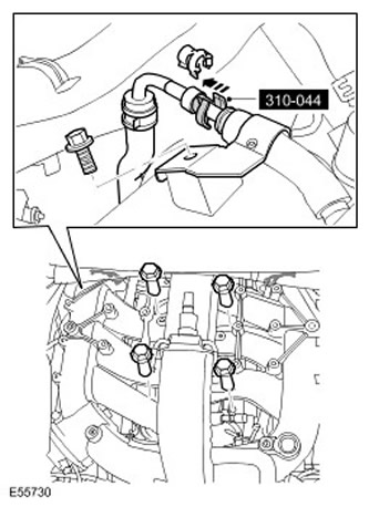
Disconnect the fuel line using a special tool.
- Remove the safety clip.
- Early models only: Remove 4 bolts and release fuel rail and fuel injectors.
- Early models only: Disconnect the left and right cylinder heads and rear fuel injector electrical connectors.
- Early models only: Remove the bolt and release the cylinder head cover fuel line clamp.
- Early models only: Secure the purge valve to the wire harness with a wire tie.
23.
CAUTION: Early models only: The purge valve and support bracket are bolted to the rear of the intake manifold and contact the fuel rail crossover line. Attempting to forcibly remove the intake manifold will cause damage. In this case, remove the inner wall and base of the battery tray on the left side to access the purge valve mounting bolt.
CAUTION: Be careful not to damage the purge valve assembly when removing the intake manifold.
NOTE: Due to the difficulty of access, it may be necessary to break the engine and transmission wiring harness clips. Be careful not to damage the wiring harnesses.
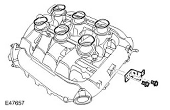
Loosen and then remove the intake manifold.
- Discard the gaskets.
- Insert plugs into the open holes.
24.
NOTE: Do not perform further disassembly if the part is removed only for access.
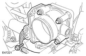
Remove the throttle body.
- Remove 4 bolts.
- Remove the throttle body gasket and discard it. Disconnect the coolant hose.
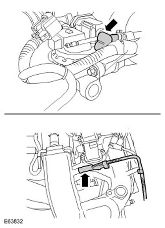
25. Disconnect the EGR valve vacuum hose. Disconnect and remove the vacuum hose from the intake manifold.
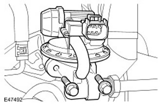
26. Remove the EGR valve.
- Remove 2 bolts.
- Select and discard the gasket.
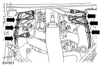
27. Remove the remaining ignition coils.
- Disconnect the spark plug wires from the coils.
- Remove the bolts and studs. Remove the seals and discard them.
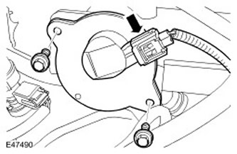
29. Remove the intake manifold adjusting valve.
- Remove 2 bolts.
- Discard the O-ring.
Installation
1.
CAUTION: After removing material, ensure there are no sharp edges.
Early models only: Remove center casting tab.
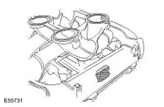
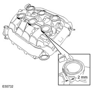
2. Early models only: Remove excess material from the outer edges of the 6 intake manifold flange surfaces.; file them down so that they are within 2mm of the edge of the gasket.
3. Early models only: Install the fuel rail and fuel injectors.
- Clean the contact surfaces of the parts.
- Tighten the bolts (tightening torque 25 Nm).
- Connect the fuel injector electrical connectors.
- Tighten the M6 bolt (tightening torque 10 Nm).
- Clean the contact surfaces of the parts.
- Install a new O-ring.
- Tighten the bolts to 10 Nm.
6.
NOTE: Mark the installation positions of the fasteners.
Install 4 ignition coils.
- Tighten the bolts (tightening torque 6 Nm).
- Tighten the studs (tightening torque 6 Nm).
- Connect the high voltage electrical connectors.
- Clean the contact surfaces of the parts.
- Install a new gasket.
- Tighten the bolts (tightening torque 25 Nm).
9. Connect the EGR vacuum hose to the intake manifold.
- Clean the contact surfaces of the parts.
- Connect the vacuum hose to the EGR valve.
- Clean the contact surfaces of the parts.
- Install a new gasket.
- Tighten the 4 bolts (tightening torque 10 Nm).
- Secure the clamp.
- Remove the hose clamp.
13.
CAUTION: Before tightening the intake manifold bolts, take precautions to ensure that the wiring harnesses, vacuum lines, and purge valve lines are not pinched.
NOTE: To make installation easier: Before installing the intake manifold, install a Torx wrench with an extension onto the left bank intake manifold Torx bolt. Secure it with tape.
NOTE: For clarity, ignition coils are not shown in the illustration.
Install the intake manifold.
- Clean the contact surfaces of the parts.
- Install the gaskets.
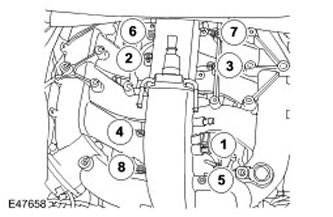
- Tighten the bolts evenly and gradually in the sequence shown. (tightening torque 10 Nm).
14. Install the remaining ignition coils.
- Tighten the bolts (tightening torque 6 Nm).
- Tighten the studs (tightening torque 6 Nm).
- Connect the high voltage electrical connectors.
16. Connect the fuel line to the fuel rail.
- Clean the contact surfaces of the parts.
- Install the clamp.
- Connect the coil ground wires.
- Tighten the nuts (tightening torque 6 Nm).
- Install and secure the clamps.
19. Connect the vacuum tube to the intake manifold.
20. Secure the purge line to the intake manifold.
- Install the spacer sleeve.
- Screw in the bolt.
- Tighten the bolt (tightening torque 6 Nm).
22. Connect the intake manifold coolant hose.
- Secure the clamp.
- Remove the hose clamp.
[The article was copied from a resource: www.lrman.ru]
24. Install the engine cover. For more information, refer to Engine Cover - 4.0L (12.30.50)
25. Attach the hood struts.
26. Connect the ground cable to the battery. For more information, refer to Specifications
27. Check the coolant level and top up if necessary.
Comments on this article