Contents: Camshaft cam lift height ⇩ Deformation (warping) mating surface…⇩ Piston pin diameter ⇩ Camshaft journal diameter ⇩ Valve stem diameter ⇩ Valve spring free length ⇩ Piston ring joint gap ⇩ Clearance between groove and piston…⇩ Crankshaft axial clearance ⇩ Axial clearance of the camshaft ⇩ Inspection of the camshaft surface ⇩ Bearing inspection ⇩ Inspection of the piston ⇩ Connecting rod lower head bore ⇩ Deviation of the cylinder bore shape…⇩ Cleaning and inspection of the…⇩ Cleaning the connecting rod ⇩ Radial clearance in the crankshaft…⇩ 6. JACK DIAMETER AND MAIN BEARING…⇩ Radial clearance in the camshaft…⇩ Matching the piston pin to the…⇩
Camshaft cam lift height
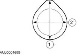
1. Measure diameter (1) and diameter (2) with a vernier caliper. The difference between these two values is the cam lift height.
Deformation (warping) mating surface of the cylinder head
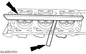
1. Measure the degree of block/cylinder head misalignment.
- Use a special tool to measure the degree of misalignment of the mating surfaces.
- If the value is not within specification, rework the mating surface.
Piston pin diameter
1.
NOTE: The piston and piston pin form a single pair. Do not confuse these elements.
Measure the piston pin diameter.
- Measure in two directions.
- If the values are not within specification, install a new piston and a new piston pin.
Camshaft journal diameter
1. Determine the diameters of the camshaft journals
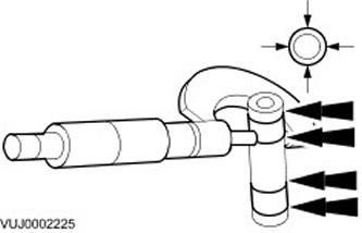
- To determine if the shaft journals are out of round, measure the diameter at 90 degree intervals using a micrometer.
- To determine if there is taper, measure the diameter of each journal at two locations offset from the journal axis.
- If the measurement results are not within the norm, install a new camshaft.
Valve stem diameter
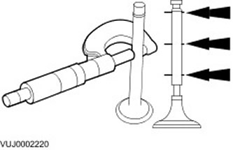
1. Measure the diameter of the valve stems with a micrometer. If the measurement result is not within the standard, install a new valve.
Valve spring free length
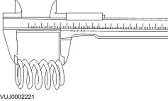
1. Using a vernier caliper, measure the free length of each valve spring. Make sure the value obtained complies with the standards.
(The article was taken from this resource: «LRman.ru»)
Piston ring joint gap
1.
CAUTION: Do not mix up the piston rings. Install the piston rings in the same position and in the same places.
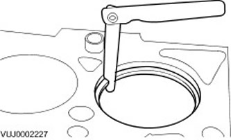
Using a feeler gauge, measure the piston ring gap. The values given in the specification apply to the gauge ring used in the manufacture of piston rings.
Clearance between groove and piston ring
1.
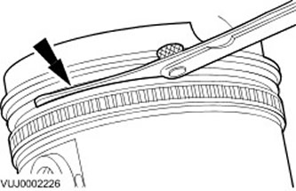
NOTE: The piston ring should protrude from the piston groove. To determine the height clearance between the groove and the ring, insert a feeler gauge directly into the groove behind the ring.
Using a feeler gauge, measure the height gap between the groove and the piston ring.
Crankshaft axial clearance
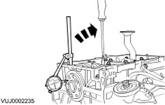
1. Using a dial indicator with brackets, measure the axial clearance.
- The measurement of the axial clearance of the crankshaft is performed by lifting the crankshaft using a lever.
- If the measured value is outside the specified limits, install new thrust washers to compensate for the backlash and repeat the measurements.
Axial clearance of the camshaft
1.
NOTE: Make sure the camshaft type is correct. (according to specification).
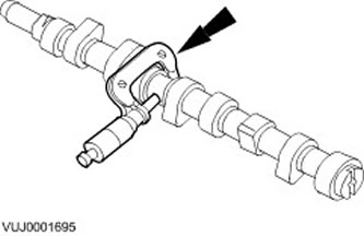
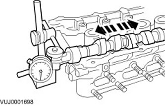
Measure the axial clearance using a special tool.
- Move the camshaft in both directions. Read and record the maximum and minimum readings on the dial indicator. The axial clearance is the difference between the maximum and minimum readings.
- If the measurement result is not within the specification, install new parts.
Inspection of the camshaft surface
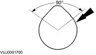
1. Inspect the camshaft lobe running surfaces for pitting or damage. Minor pitting outside the running surface is acceptable.
Bearing inspection
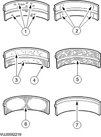
Inspect the bearings for the following defects.
- 1. Painting (formation of holes) - fatigue wear.
- 2. Polished in places - incorrect fit.
- 3. Embedded particles - contaminated engine oil.
- 4. Scratches - contaminated engine oil.
- 5. Scoring - poor lubrication.
- 6. Wear of both edges - damage to the neck.
- 7. Wear on one edge - neck taper or incorrect fit.
Inspection of the piston
CAUTION: Do not use aggressive cleaning fluid or wire brush to clean the piston.
Perform a visual inspection.
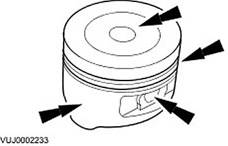
- Clean the piston skirt, piston pin bushing, piston grooves and crown and inspect them for wear and cracks.
- If there are signs of wear on the piston skirt, check that the connecting rod is not deformed or twisted.
Connecting rod lower head bore
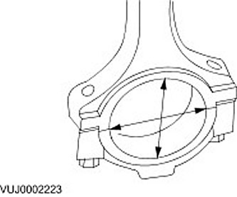
1. Measure the connecting rod head bore in two directions. The difference in measurements is the deviation of the connecting rod head bore from roundness. (ovality). Make sure that the deviation from roundness is within the norm.
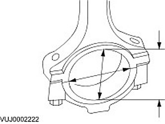
2. Measure the connecting rod head bore diameter in two directions. Make sure that the connecting rod head bore diameter is within the standard.
Deviation of the cylinder bore shape from roundness
1.
NOTE: The main bearing caps must be in place and tightened to the specified torque. However, the bearing shells must not be installed.
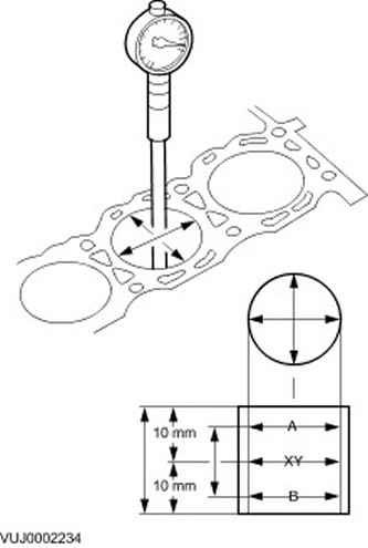
Use a bore micrometer to measure the cylinder bore diameter.
- To determine if there is any deviation of the cylinder shape from roundness or taper, take measurements in different directions and at different heights.
- If the measurement result is not within the standard, hone the cylinder block or install a new cylinder block.
Cleaning and inspection of the exhaust manifold
1. Inspect the exhaust manifold flanges that connect to the cylinder head for signs of exhaust leakage.
2. Inspect the exhaust manifold for cracks, damage to the gasket surfaces, or other damage that may render the manifold unsuitable for subsequent use.
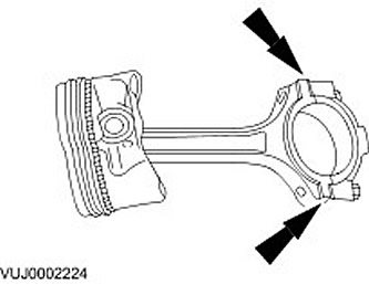
Cleaning the connecting rod
CAUTION: To avoid damaging the connecting rods, do not use a caustic cleaner solution.
Mark and separate the connecting rod into its component parts and clean them with solvent. Clean the oil passages.
Radial clearance in the crankshaft main journal
CAUTION: These procedures should not be performed while under the manufacturer's warranty.
1.
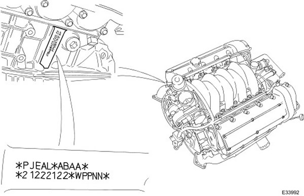
NOTE: Example - *PJEAL* - Crankshaft journal diameter.
Read the class letters from LEFT to RIGHT = FROM FRONT to REAR of the engine. For example, on this engine, the crankshaft journal at the front of the engine is a P and at the rear of the engine is an L. The selection of main bearing shells is described in the following table.
2.
NOTE: Example - *ABAA* - Crankpin Diameter (lower connecting rod bearing).
NOTE: For vehicles manufactured prior to model year 2002.
NOTE: If the crankshaft main bearing housing bolts have been spotted, they must be discarded and new bolts installed.
Read the class letters from LEFT to RIGHT = FROM FRONT to REAR of the engine. For example, on this engine, the crankshaft journal at the front of the engine is an A, and at the rear of the engine, it is also an A.
- Class A = 56,000 - 55,994 mm (bearing shell color code - blue).
- Class B = 55.994 - 55.988 mm (bearing shell color code - green).
- Class C = 55.988 - 55.982 mm (bearing shell color code - yellow).
3.
NOTE: Example - *ABAA* - Crankpin Diameter (lower connecting rod bearing).
NOTE: For vehicles manufactured from model year 2002 onwards.
NOTE: If the crankshaft main bearing housing bolts have been spotted, they must be discarded and new bolts installed.
Read the class letters from LEFT to RIGHT = FROM FRONT to REAR of the engine. For example, on this engine, the crankshaft journal at the front of the engine is an A, and at the rear of the engine, it is also an A.
- Class A = 53,000 - 52,994 mm (bearing shell color code - blue).
- Class B = 52.994 - 52.988 mm (bearing shell color code - green).
- Class C = 52.988 - 52.982 mm (bearing shell color code - yellow).
4.
NOTE: Example - *21222122* - Cylinder and piston.
The cylinder diameter class is read from LEFT to RIGHT as follows:
- Cylinder bank 2 - cylinder 1, cylinder bank 2 - cylinder 2, cylinder bank 2 - cylinder 3, cylinder bank 2 - cylinder 4, cylinder bank 1 - cylinder 4.
- Cylinder bank 1 - cylinder 3, cylinder bank 1 - cylinder 2, cylinder bank 1 - cylinder 1.
- (Please note that in early publications, cylinder bank 1 was referred to as cylinder bank A and cylinder bank 2 as cylinder bank B.)
- Class 1 cylinder diameter = 85.990 - 86.000 mm.
- Class 2 cylinder diameter = 86.000 - 86.010 mm.
- Class 3 cylinder diameter = 86.010 - 86.020 mm.
5.
NOTE: Example - *WPPNN* - Crankshaft main bearing bore diameter in cylinder block
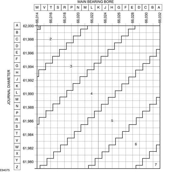
Read the class letters from LEFT to RIGHT = FROM FRONT to REAR of the engine. For example, on this engine the crankshaft journal at the front of the engine is a W and at the rear of the engine is an N. The selection of main bearing shells is described in the following table MAIN BEARING JOURNAL DIAMETER AND BORE.
6. JACK DIAMETER AND MAIN BEARING BORE
7.
NOTE: THIS PROCEDURE SHOULD ONLY BE PERFORMED WHEN REPLACING MAIN BEARING LINERS.
NOTE: Refer to the MAIN BEARING JOURNAL DIAMETER AND BORE table in item 6 for tolerances and bearing information.
The number in each diagonal stripe represents the PAIR of color-coded main bearing shells to be used on a specific journal, based on the journal diameter and bore diameter combination. The color codes for each stripe are as follows:
- Blue/green and blue/green
- Blue/green and blue
- Blue and blue
- Blue and green
- Green and green
- Green and yellow
- Yellow and yellow
- Let's look at the crankshaft journal 5 (from the example of the class marking on the cylinder block) - the cylinder block bore is class N, and the crankshaft journal diameter is class L. From this table it will be seen that the intersection point is in strip 4, which corresponds to one blue bearing and one green bearing.
- Once the appropriate pair of color codes has been selected for a journal, the bearing of either color can be installed on the cylinder block or on the backing plate, but the bearing to be installed on the cylinder block must have an oil groove, while the bearing for the backing plate must be of a normal, flat design.
8.
NOTE: THIS PROCEDURE SHOULD ONLY BE PERFORMED WHEN REPLACING THE CRANKSHAFT OR CYLINDER BLOCK.
NOTE: Refer to the MAIN BEARING JOURNAL DIAMETER AND BORE table in item 6 for tolerances and bearing information.
The thickness class for all main bearing shells shall be selected to obtain a total radial clearance of not less than 0.022 mm and not more than 0.040 mm.
- The bore diameter for each bearing in the cylinder block/support plate should be measured at two mutually perpendicular locations at an angle of 45° to the vertical in the middle of the bearing.
- The smallest of the two diameter values should be used.
- The diameter of each crankshaft main journal should be measured dynamically at a point corresponding to the middle of each bearing.
- Once the appropriate pair of color codes has been selected for a journal, the bearing of either color can be installed on the cylinder block or on the backing plate, but the bearing to be installed on the cylinder block must have an oil groove, while the bearing for the backing plate must be of a normal, flat design.
Radial clearance in the camshaft journal
1.
NOTE: Follow the prescribed procedure carefully. The valve lifters must be removed to perform the following measurements.
NOTE: Make sure the camshaft type is correct. (according to specification).
NOTE: Bearing caps and camshaft journals must be clean and free of oil.
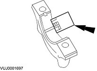
Place a piece of Plastigage clearance gauge thread on the bearing cap.
- Install the camshaft into the cylinder head without lubricating it.
- Place a Plastigage clearance gauge thread equal in length to the width of the bearing cap on the appropriate journal.
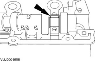
2. Install the camshaft bearing caps. Tighten the fasteners in the sequence shown.
3.
NOTE: Do not hit the bearing caps.
Remove the camshaft bearing caps. Loosen the fasteners in the sequence shown.
4. Take measurements with a special tool.
- Compare the width of the Plastigage thread with the corresponding scale.
- The scale reading corresponds to the radial clearance in the bearing.
- If readings are not within specification, install a new camshaft.
Matching the piston pin to the piston hole
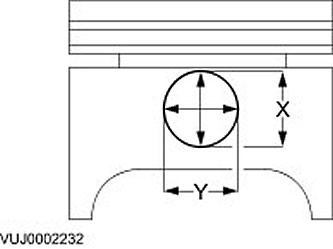
1.
NOTE: The piston and piston pin form a single pair. Do not confuse these elements.
Measure the piston pin bore diameter.
- Measure in two directions.
- If the values are not within specification, install a new piston and a new piston pin.
Comments on this article