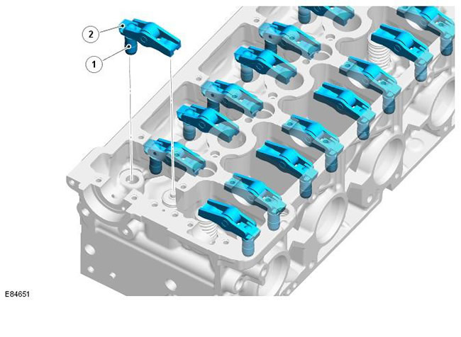
| Pos. | Spare part number | Name |
| 1 | - | Hydraulic clearance compensator |
| 2 | - | Roller valve lever |
The 16 valves are actuated by roller rocker arms and hydraulic lash adjusters, which in turn are actuated by the camshaft lobes. One end of the rocker arm rests on the end of the valve stem, the other end is attached to the hydraulic lash adjuster. In the center of the rocker arm is a roller that remains in contact with the camshaft lobes.
Typical hydraulic clearance compensator
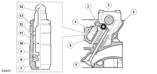
| Pos. | Spare part number | Name |
| 1 | - | Oil channel |
| 2 | - | Roller valve lever |
| 3 | - | Camshaft |
| 4 | - | Cylinder head |
| 5 | - | Valve |
| 6 | - | Hydraulic clearance compensator |
| 7 | - | Plunger spring |
| 8 | - | High pressure chamber |
| 9 | - | Ball valve |
| 10 | - | Plunger |
| 11 | - | Tank chamber |
| 12 | - | Oil channel |
| 13 | - | Hydraulic clearance compensator housing |
| 14 | - | Plunger cap |
When moving, the camshaft cam presses on the roller valve lever and, therefore, the force acts on the hydraulic clearance compensator and the valve mechanism. The corresponding valve is pressed under the action of the valve spring pressure, the hydraulic plunger is also pressed into the oil chamber in the cylinder head. This valve drive mechanism minimizes friction between the working elements of the valve and eliminates the need for mechanical adjustment.
The hydraulic clearance compensator housing contains a plunger and two chambers for oil supply and pressurized oil. Pressurized oil is supplied to the clearance compensator through an oil gallery in the cylinder head and through an opening in the side of the clearance compensator housing. The oil passes into the supply chamber of the clearance compensator and then into a separate discharge chamber through a one-way ball valve.
The oil flow from the discharge chamber is determined by the size of the gap between the outer housing and the central plunger of the clearance compensator. Each time the clearance compensator is activated, oil flows out along the wall of the plunger. The pressure pressing the plunger displaces the corresponding volume of oil in the housing of the clearance compensator.
As the camshaft cam rotates further, the force acting on the camshaft and valve lever is removed. The plunger of the clearance compensator is pushed upward by the pressure of the oil in the pressure chamber. This pressure is not enough to affect the operation of the valve, but it is enough to eliminate the gap between the valve lever and the top of the valve stem.
The article was taken from this resource: LRMAN.ru
Comments on this article