


Contents: Arrangement of elements ⇩ Review ⇩ Fuel tank filler neck with cap ⇩ Fuel tank ⇩ Possible fuel tank capacities ⇩ Fuel tank ventilation system ⇩ Fuel level sensor ⇩ Fine fuel filter ⇩ Fuel cooler ⇩ Air release valve ⇩ Fuel lines ⇩ Low fuel level indication and…⇩
Arrangement of elements
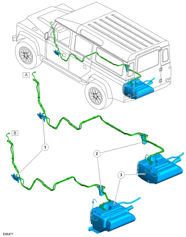
| Pos. | Spare part number | Name |
| A | - | Option 110 |
| B | - | Option 90 |
| 1 | - | Fuel system radiator |
| 2 | - | Fuel filter |
| 3 | - | Fuel tank |
Review
The fuel supply system includes a filler pipe and flexible pipeline, a fuel tank (including sensor assembly and ventilation system), fuel filter, fuel cooler, bleed valve and connecting fuel lines.
The fuel system supplies fuel to the engine via a booster pump, which is an important component of the engine's built-in injection pump. The fuel system is a rarefied system with a pressure drop across the booster pump of 20-30 kPa.
The return flow from the engine returns to the filter. To prevent waxing of the filter at low temperatures, a thermostatic diverter directs the heated return flow back through the filter to the engine. At higher temperatures, the return flow is diverted back to the tank.
Fuel tank filler neck with cap
The fuel filler neck is located on the panel in the right rear quarter panel, behind the door. The door is opened by an electrical switch on the instrument panel that operates a release solenoid.
The filler hole is closed by a plastic cap on a thread, screwed onto its neck. The cap is equipped with a ratchet mechanism to prevent its excessive tightening and provides a seal of the neck, preventing the release of fuel vapors. The filler cap has a valve that releases excess fuel pressure into the atmosphere at approximately 0.12 - 0.13 bar and opens in the opposite direction at a vacuum of about 0.04 bar.
The filler hole is connected to the fuel tank via a molded flexible high-density polyethylene (HDPE) hose.
Fuel tank
The fuel tank is located at the rear of the vehicle, below, between the chassis side members.
The support is attached to the chassis with six screws. When the support is attached to the chassis, the tank is protected by foam pads that fit against the center crossmember of the chassis. Additional protection is provided by a protective cover that is installed in the front right corner of the tank.
The fuel tank is made of HDPE. The fuel tank is a sealed unit with the only possible access to the inside through the hole in the flange of the fuel pump module located in the upper part of the tank.
The reflective metal cover is attached to the tank with two threaded rivets and serves to protect the tank from heat generated in the exhaust system.
Possible fuel tank capacities
| Option | Fuel tank capacity |
| 90 | 56 l |
| 110 | 70 l |
Fuel tank ventilation system
The filler pipe is equipped with a ventilation system, thanks to which air and fuel vapors are forced out of the tank during refueling and released into the atmosphere through the filler neck.
The breather outlet in the tank serves to control the "full" height of the tank. When fuel covers the outlet, the escape of fuel vapors and air from the tank is blocked. This results in "backfilling" of the filler neck with fuel and shutting off the fuel nozzle. The location of the outlet is such that when the fuel nozzle is disconnected, the space for fuel vapors is approximately 10% of the total tank capacity. Due to the arrangement of the vapor space, the Roll Over Protection Valve (ROV) is always above the fuel level, as a result of which vapors can escape and provide ventilation of the tank.
The ROV is welded to the top of the tank. The ROV is connected to the vent line to the atmosphere. The ROV allows fuel vapor to pass through it under normal vehicle operating conditions. In the event of a vehicle rollover, the valve closes, ensuring the tank is sealed and preventing fuel from leaking through the vent line to the atmosphere.
The vent line to the atmosphere includes a two-way valve that allows pressure relief in one direction and air flow into the tank when the system is operating under vacuum.
Fuel level sensor
The fuel level indicator sensor is located inside the fuel tank. Access to the sensor assembly is through an opening in the top of the tank. The flange of the unit is fixed in the working position and sealed with a steel retaining ring.
The fuel sensor assembly includes a top cover flange containing an electrical connector for connecting the sensor and two steel fuel line connections.
The flange is sealed by a rubber seal installed between this flange and the body of the retaining ring.
The top cover is attached to the vortex chamber assembly by two spring-loaded steel posts. The springs securely hold the vortex chamber to the bottom of the tank.
The vortex chamber ends with a cavity in which the fuel level indicator sensor is located.
The swirl chamber serves the function of preserving the fuel reserve, ensuring that the fuel is always taken below its level. This is achieved by directing a reverse flow into the swirl chamber, and the jet pump provides additional flow into the chamber, formed by the fuel remaining in the tank, and the jet pump is provided with the reverse flow. In addition, at the base of the swirl chamber unit there is a bypass valve. When the fuel tank is full, the fuel pressure keeps the valve raised above the seat, and fuel can enter the swirl chamber. As the fuel level in the tank decreases, the fuel pressure in the tank drops, and as a result, the valve closes. When the valve is closed, the fuel is retained in the swirl chamber.
Flexible pipes connected to the top cover provide fuel supply to and return from the swirl chamber.
The fuel level indicator sensor is equipped with a potentiometer, which works with the help of a float element.. The float element rises and falls depending on the fuel level in the tank and, accordingly, moves the potentiometer.
The voltage to the potentiometer is supplied from the instrument panel. The output resistance of the potentiometer changes depending on the fuel level. This resistance is displayed on the instrument panel using the fuel gauge.
The indicator mounted on the instrument panel turns on when the amount of fuel in the tank drops to 10 liters.
Roll Over Protection Valves (ROV)
The two ROVs are located on the fuel tank support structure and are connected by tubes to the fuel vapor separator. The phase separator, also mounted on the inner bracket, is connected by tube to the fuel tank vent fitting on the fuel lift pump flange. The ROVs contain check valves that close when the vehicle rolls over, preventing liquid fuel from leaking from the tank through the breather tube.
Fine fuel filter
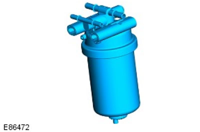
The fuel filter removes solid particles from the fuel and also separates out water that collects at the bottom of the filter.
The fuel filter is located on the chassis to the right of the fuel tank. Fuel supplied to and returned from the engine passes through the filter. Connections are made using quick-release devices.
The rear steel cover is secured to the chassis side member using four M8 threaded screws.
The filter is screwed to the mounting plate with two M8 threaded bolts.
The steel protective cover is fixed to the back cover by means of a special lock with a 1/4 turn rotation.
The filter is equipped with an internal air bleed device, which ensures that air enters the engine together with fuel only in small, regulated quantities.
The thermostatic diverter valve is completely closed at 45 degrees Celsius and directs fuel directly into the tank. When the diverter is open, fuel is recirculated through the filter to the engine.
The fuel filter is equipped with a replaceable filter element of the cartridge type with a threaded mount, which is sealed against the filter housing with rubber seals. The lower section of the cartridge is equipped with a threaded tip for draining water.
The cartridge life before replacement is 24,000 miles.
In countries where low quality fuel is used, the cartridge life may be reduced.
Fuel cooler
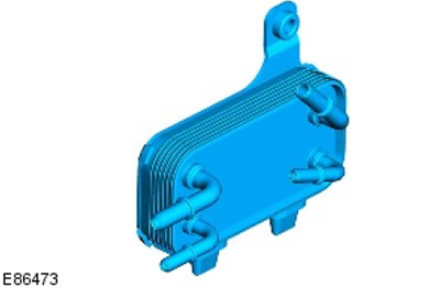
The fuel cooler uses coolant from the radiator to reduce the temperature of the fuel returning to the tank from the high pressure fuel pump.
The cooler is fixed to a bracket, which in turn is attached to the inner left chassis rail. The bracket has two slots into which the plastic projections of the cooler housing are inserted. The cooler is attached to the bracket using an M8 threaded bolt.
The cooler is equipped with four quick-release connections. Fuel inlet and outlet; supply and return of coolant.
Air release valve
The air release valve is located on the fuel line near the injection pump. It facilitates connection to the vacuum when filling the fuel system and removing air during refueling. This helps protect the injection pump from air locks.
Fuel lines
Three fuel lines in an assembly form a connection through which fuel is supplied and returned from the tank to the filter, from the filter to the cooler, and from the cooler to the engine.
These fuel lines are made of 1mm thick conductive nylon with a 2mm thick fire retardant Santoprene coating and an anti-abrasive coating. The diameter of the feed line is always larger than the diameter of the return line.
Low fuel level indication and "run-dry" strategy
The "run-dry" strategy is used to maintain the fuel system filling level close to the fuel depletion conditions. It ensures that a minimum amount of fuel always remains in the swirl chamber.
A yellow light comes on on the instrument panel to warn of low fuel level, (next to the fuel gauge), that is, that there is no more than 15% left in the tank. The fuel level indicator indicates that the tank is empty when there is still 11% of fuel left in the tank.
When 4 liters (1.2 gallons) of fuel remain in the tank, the "run-dry" strategy is initiated. The engine will misfire for approximately 1 mile (1.6 km), after which the engine will shut down. The engine can be restarted in the misfire mode, and will continue to run for another mile before the engine dies again. This can be repeated until the inlet in the tank is above the fuel level, at which point the engine will begin to starve for fuel and eventually lose power. Restarts after stops in the "run-dry" mode are not recommended.
Comments on this article