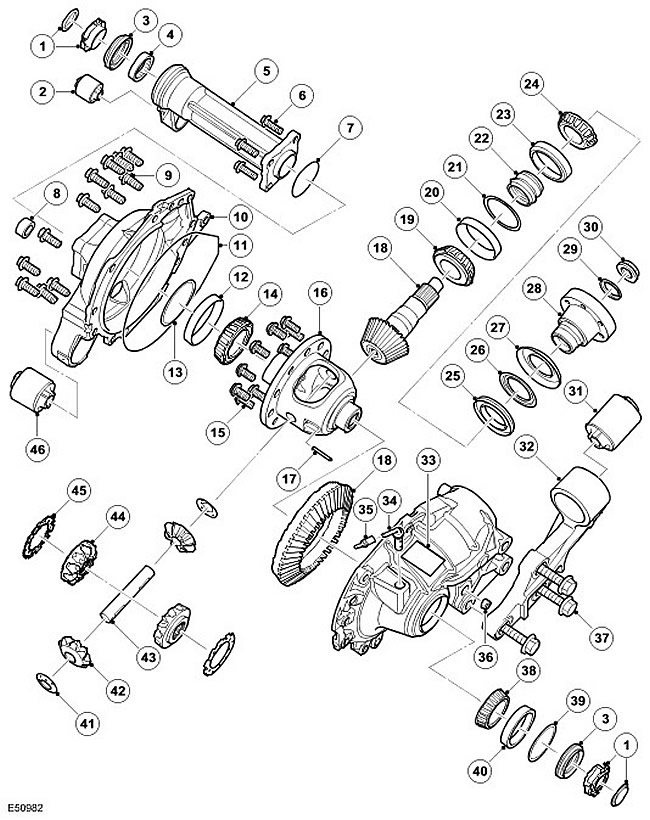
| Item name | Spare part number | Description |
| 1 | - | protective cap |
| 2 | - | Mounting sleeve assembly |
| 3 | - | Seal |
| 4 | - | Bearing assembly |
| 5 | - | front tube |
| 6 | - | Bolt, 4 pcs. |
| 7 | - | Sealing ring |
| 8 | - | drain plug |
| 9 | - | Bolt, 14 pcs. |
| 10 | - | Lid assembly |
| 11 | - | Cover seal |
| 12 | - | Roller bearing outer ring |
| 13 | - | Bearing preload spacer |
| 14 | - | Tapered roller bearing |
| 15 | - | Bolt, 10 pcs. |
| 16 | - | Differential housing |
| 17 | - | cylindrical pin |
| 18 | - | Gear assembly |
| 19 | - | Tapered roller bearing |
| 20 | - | Roller bearing outer ring |
| 21 | - | Washer |
| 22 | - | Deformable spacer |
| 23 | - | Roller bearing outer ring |
| 24 | - | Tapered roller bearing |
| 25 | - | Oil seal |
| 26 | - | Internal deflector |
| 27 | - | Outer deflector |
| 28 | - | Flange |
| 29 | - | Pinion nut lock |
| 30 | - | Pinion nut |
| 31 | - | Mounting sleeve assembly |
| 32 | - | Bridge Support Bracket |
| 33 | - | information plate |
| 34 | - | breather tube |
| 35 | - | Lid |
| 36 | - | Filler plug |
| 37 | - | Bolt, 3 pcs. |
| 38 | - | Tapered roller bearing |
| 39 | - | Bearing preload spacer |
| 40 | - | Roller bearing outer ring |
| 41 | - | thrust washer |
| 42 | - | planetary gear |
| 43 | - | Shaft |
| 44 | - | sun gear |
| 45 | - | thrust washer |
| 46 | - | Mounting sleeve assembly |
The body consists of two halves with machined contact surfaces. In the assembled state, the junction of the cast-iron body halves is sealed with a thin film of Loctite 5999 sealant, and the halves themselves are fastened with 14 bolts. A breather tube is connected to the housings. This allows a plastic tube to be installed and led out at a high point in the engine compartment to prevent water from entering while the vehicle is wading.
The right half of the housing is equipped with a drain plug. The capacity of the front differential is approximately 0.7 liters when dry filled.
The differential has a traditional hypoid gear design. It uses a driven gear and a bevel hypoid pinion shifted upward relative to the axis of the driven gear. This design allows the use of a larger drive gear, which increases its strength and reduces noise during operation.
There are 3 types of front differentials with different gear ratios. Vehicles with V8 and V6 gasoline engines use a front differential with a final drive ratio of 3.73:1. In vehicles with a Tdv6 diesel engine and automatic transmission, the final drive ratio is 3.54:1, and with a manual transmission it is 3.07:1. Changing the number of teeth between the driven gear and the final drive gear results in a change in gear ratio.
The differential consists of a pinion shaft, a hypoid bevel gear and a driven final drive gear with an integral housing housing 2 planetary gears. The housing also houses 2 sun gears that transmit torque to the drive shafts.
The pinion shaft is mounted on 2 opposing tapered roller bearings with a deformable sleeve in between. The sleeve is used to center the bearings and, moreover, is deformed when force is applied to the gear nut. This allows the nut to be tightened to a predetermined torque, at which the sleeve is deformed, providing the required bearing preload.
The pinion shaft has an externally splined outer end that engages with the primary flange, which is secured with the pinion nut. The opposite end of the output flange has internal slots for rigid fixation of the front propeller shaft. The flange is provided with an external O-ring that seals the front propshaft boot to keep dirt and moisture out of the splines. An oil seal is pressed into the left crankcase, which seals the connection of the primary flange with the differential. From the inner end of the gear shaft, a bevel hypoid gear is installed, which engages with the driven gear of the final drive.
The driven gear is located on the cup and is fixed with 10 screws. The cup is mounted on tapered roller bearings located in each half of the body. The bearings are pressed into the housing, and a spacer bushing is installed on the outside, which regulates the side clearance and provides the bearing preload.
The cup is equipped with a shaft on which 2 planetary gears are fixed. The shaft is attached to the cup with a cylindrical pin. The sun gears are located in the recesses of the cup and engage with the planetary gears. Thrust washers are installed between the sun gears and the cup, which ensure the engagement of the sun gears with the planetary gears. Each sun gear has a machined splined hole for the drive shaft. A groove is machined in the hole for a retaining ring, which is installed on the drive shaft, ensuring its rigid fixation.
Comments on this article