Before disconnecting the battery, make sure that all the requirements and conditions contained in the section on disconnecting the battery are met.
GENERAL INFORMATION, Precautions when working with electrical equipment.
Dismantling
1. Follow all safety rules when working with passive safety systems.
GENERAL INFORMATION, Safety Precautions When Working on the Airbag System (SRS).
2. Drain the coolant from the cooling system.
COOLING SYSTEM: Td6, ADJUSTMENTS AND MAINTENANCE, Coolant drain, system flush and fill.
3. Empty the air conditioning system and collect the refrigerant.
AIR CONDITIONING SYSTEM, AIR CONDITIONER DRAINAGE, REFRIGERANT RECOVERY AND CHARGING, Air Conditioner Emptying - Refrigerant Recovery and Charging.
4. Remove the air intake box.
HEATING AND VENTILATION, REPAIR WORKS, Air intake box.
5. Remove the front seats.
SEATS, REPAIRS, Front seat.
6. Remove the heater control unit.
HEATING AND VENTILATION, REPAIR WORKS, Controls - heater (electronic control unit) (ECU).
7. Remove the air suspension control panel.
CAR INTERIOR PARTS, REPAIR WORKS, Switch panel - air suspension.
8. Remove the parking brake lever assembly.
BRAKE SYSTEM, REPAIRS, Lever assembly - parking brake.
9. Remove the control panel bottom shields.
CAR INTERIOR PARTS, REPAIR WORKS, Side panel - center console.
10. Release and remove the air ducts of the HEVAC unit.
11. For left-hand drive vehicles: Remove the driver's left footrest.
CAR INTERIOR PARTS, REPAIR WORKS, Foot support frame - left hand drive.
12. Install the bottom trim of the rack "A".
CAR INTERIOR PARTS, REPAIR WORKS, Overlay - rack " A" - bottom.
13. Remove the upper pads of the racks "A".
CAR INTERIOR PARTS, REPAIR WORKS, Overlay - rack "A" - top.
14. Remove the top overlay of the control panel from outside the driver.
VEHICLE INTERIOR PARTS, REPAIR WORKS, Control panel top trim - driver's side.
15. Remove the top overlay of the control panel from outside the passenger.
VEHICLE INTERIOR PARTS, REPAIR WORKS, Control panel top trim - passenger side.
16. Remove the automatic transmission selector assembly.
AUTOMATIC TRANSMISSION - GM 5L40-E, REPAIR WORK, Selector lever - gear selector assembly.
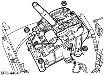
17. Turn away 4 nuts of fastening of a support of the selector, remove a support of the selector.
18. Cover protruding parts to prevent damage to the control panel during removal.
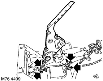
19. Turn out 4 screws of fastening of an arm of a lay brake to a body and remove an arm.
20. Turn out 4 screws fastening a support of the central console to a body and remove a support.
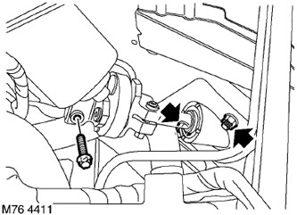
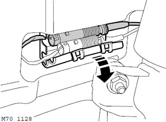
21. Noting the fixed position, remove the Torx screw of the clamp connecting the lower and intermediate steering shafts of the steering column
22. Turn away 2 nuts of fastening of a support of a steering shaft, separate a support from a body and disconnect steering shafts.
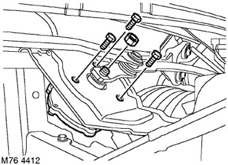
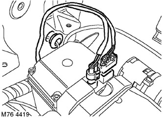
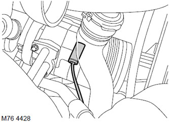
23. Having noted the fixed position, turn away a nut and disconnect draft from the screen wiper electric motor.
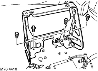
24. Turn out 3 screws of fastening of a screen wiper drive, remove the drive with the electric motor and move aside for access.
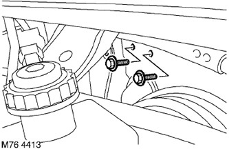
25. Turn away 2 screws of fastening of the control panel to a partition of a motor compartment.
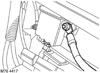
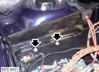
26. Remove 2 Allen type screws securing A/C piping to baffle, disconnect piping, remove and discard O-rings.
WARNING: Cap all openings immediately to prevent dirt and moisture from entering the system.
27. Install a container to collect escaping coolant.
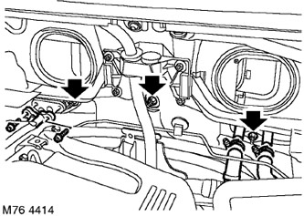
28. Loosen the clamps and remove the heater system hoses from the connecting plate on the bulkhead.
29. Turn away 3 nuts of fastening of knot of a heater to a partition.
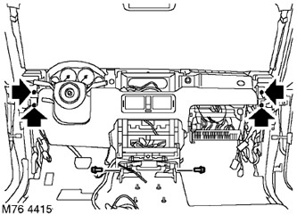
30. Turn away 4 nuts and 2 screws of fastening of the control panel to a body.
31. Cover the bottom brackets of the control panel so as not to damage the carpeted floor.
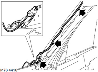
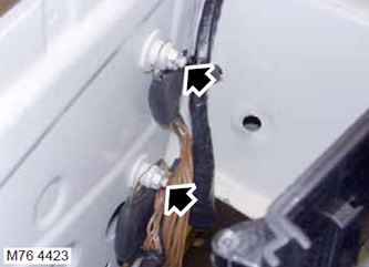
32. Disconnect the 2 connector blocks and release the cable harness retainer from the rack "A" near the lower edge of the windshield. Repeat the operation on the other side of the control panel. Tape the disconnected cables to the windshield.
33. Move the control panel far enough so that you can disconnect the airbag connector blocks at the pillar "A".
34. For passenger side only. Release the 2 additional cable harness clips on the stand "A".
35. Remove the transfer box electronic control unit.
TRANSFER BOX, REPAIR WORKS, Electronic control unit - transfer case.
36. Disconnect "positive" cable from the fuse box under the control panel.
37. Disconnect the relay and the block from the fuse box under the control panel.
38. Release the cable harness from the bulkhead and take it aside.
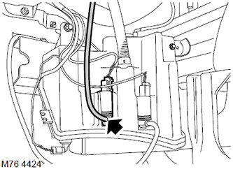
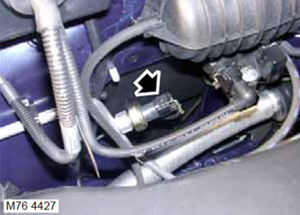
39. Disconnect 2 blocks from a socket of a fuel preheater if it is established.
40. Disconnect the cable from the side turn signal repeater, release the inner wing rubber grommet and pull out the cable.
41. Remove both wheel arch liners.
EXTERIOR PARTS, REPAIR WORKS, Fender liner - front wheel arch.
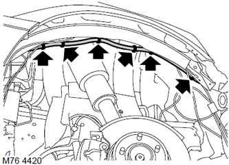
42. Release the wiring harness from the retainers on the inner fender.
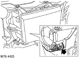
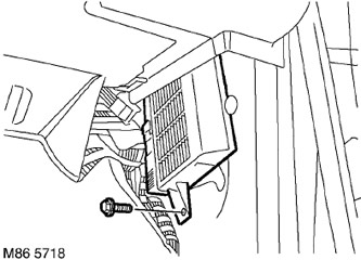
43. Remove the 10 Allen type screws securing the electronics compartment cover and remove the cover.
44. Remove the 2 screws securing the electronics compartment in the engine compartment and move it to the side for access.
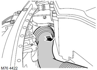
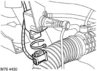
45. Release and remove the air inlet from the inner wing.
46. Turn away nuts and disconnect tips "masses" cable harness.
47. Remove the front bumper.
EXTERIOR PARTS, REPAIR WORKS, Front bumper assembly.
48. Disconnect the hose from the rear window washer pump.
49. Release the 4 flexible clips securing the washer hose to the bumper beam and move the hose to the side.
50. Disconnect the horn block.
51. Remove the turn signal lamp.
LIGHTING, REPAIRS, Front Combination Lamp - Parking Light and Turn Signal.
52. Disconnect the headlight connector block.
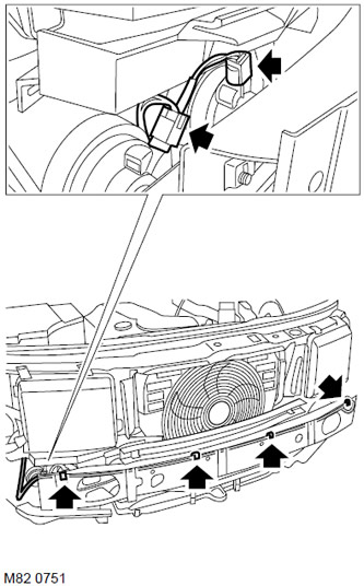
53. Mark the position of the clamps of the cable of the sensor of the vertical position of the body, remove the clamps and disconnect the connector block.
54. Disconnect the connector blocks from the radiator unit.
55. Disconnect the connector from the ABS sensor.
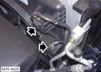
56. Disconnect the connector block from the air conditioner switch.
57. Disconnect the connector block from the air conditioning compressor.
58. Remove the connector block of the steering angle sensor.

59. Remove the screw securing the lighting control module to the rack "A".
60. Move the light control module to the side.
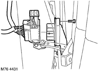
61. Remove the screw securing the door harness connector block to the rack "A" and disconnect the connector block.
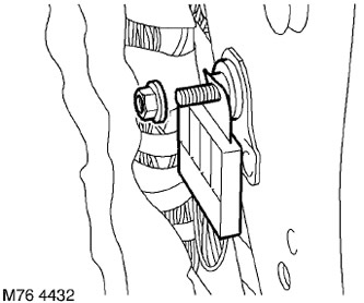
62. Remove the terminal nut "masses" to the rack "A" and remove the clamp.
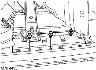
63. Raise the carpet and remove the 3 clips securing the protective screen of the cable harness to the body, release and remove the screen.
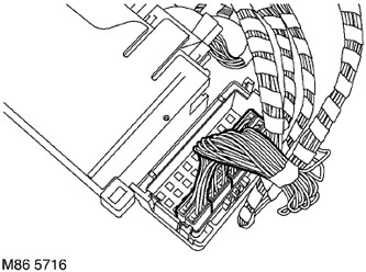
64. Release the retainer that secures the connector to the body control computer bracket (BSU).
65. Remove 2 nuts and slide the control computer body equipment (BCU) to the side.
66. Release the main cable harness from the channel and lay the carpet in place.
67. With the help of an assistant, pull the harness through the bulkhead of the engine compartment and rotate the control panel assembly for access for other work.
CAUTION: Check that the evaporator piping is not damaged when moving the control panel.
68. Support the control panel on a suitable stand to prevent damage to the floor carpet and decorative pieces.
Assembly
1. With the help of a second person, position the cable harnesses and control panel on the bulkhead of the engine compartment.
2. Attach the airbag and rack connectors "A".
3. Raise the carpet, lay the cable harness, install the protective screen and secure it with clips.
4. Lay and fix the carpet.
5. Install and secure the BCU computer bracket.
6. Install and secure the terminal "masses" on the counter "A".
7. Attach the door harness connector block and secure it with the screw.
8. Install and secure the lighting control module.
9. Route the cable harness, connect the pads to the connectors of the radiator block, air conditioning switch, compressor, ABS sensor and vertical position sensor. Check that the body height sensor cable and cable clamps are properly secured.
10. Connect a block to a socket of the gauge of an angle of rotation of a steering shaft.
11. Attach blocks of sockets of a sound signal and a headlight.
12. Establish the forward combined lantern of dimensional light and index of turn.
LIGHTING, REPAIRS, Front Combination Lamp - Parking Light and Turn Signal.
13. Attach a hose of a washer of back glass.
14. Position the washer hose on the bumper beam and secure it with flexible clamps.
15. Reinstall the front bumper.
EXTERIOR PARTS, REPAIR WORKS, Front bumper assembly.
16. Install the bracket of the electronic units in place and tighten the mounting bolts with a torque of 3 Nm.
17. Install the cover of the electronics compartment, tighten the Allen type screws and tighten them with a torque of 2 Nm.
18. Attach the cable harness to the inner fender.
19. Reinstall and secure both wheel arch liners.
EXTERIOR PARTS, REPAIR WORKS, Fender liner - front wheel arch.
20. Lay the cable, install and secure the turn signal repeater lamp.
21. Position the cable, install and secure the oil heater connector block.
22. Attach the relay to the fuse box under the control panel.
23. Attach "positive" cable to the fuse box under the control panel.
24. Install the transfer case electronic control unit.
TRANSFER BOX, REPAIR WORKS, Electronic control unit - transfer case.
25. Establish the control panel on a partition of a motor compartment, wrap nuts and screws and tighten them with the moment of 25 Нм.
26. Secure the cable harness with the clamps on the stand "A".
27. Screw the nuts securing the HEVAC unit to the bulkhead of the engine compartment and tighten them with a torque of 10 Nm.
28. Connect the cooling system hoses and secure them with clamps.
29. Lubricate the new O-rings with clean special oil and install them on the pipes and hoses.
30. Position the air conditioning piping on the bulkhead, tighten the mounting screws and tighten them with a torque of 25 Nm.
31. Wrap screws of fastening of the control panel to a partition of a motor compartment and tighten them with the moment of an inhaling of 25 Нм.
32. Position the wiper drive, install the screws and tighten them with a torque of 10 Nm.
33. Attach the wiper linkage to the drive, install the nut and tighten it with a torque of 25 Nm.
34. Assemble the steering column, install the steering shaft support, tighten the fastening nuts and tighten them with a torque of 25 Nm.
35. Wrap the Torx screw in the collar of the lower steering shaft and tighten it with a torque of 25 Nm.
36. Establish a support of the central console and tighten screws with the moment of 10 Нм.
37. Establish an arm of the lever of a parking brake on a body, wrap screws and tighten them with the moment of 25 Н·м.
38. Reinstall the automatic transmission selector bracket and tighten the nuts to 25 Nm.
39. Install the automatic transmission selector assembly.
AUTOMATIC TRANSMISSION - GM 5L40-E, REPAIR WORK, Selector lever - gear selector assembly.
40. Establish the top overlay of the control panel from outside the passenger.
VEHICLE INTERIOR PARTS, REPAIR WORKS, Control panel top trim - passenger side.
41. Establish the top overlay of the control panel from outside the driver.
VEHICLE INTERIOR PARTS, REPAIR WORKS, Control panel top trim - driver's side.
42. Install the top strut covers "A".
CAR INTERIOR PARTS, REPAIR WORKS, Overlay - rack "A" - top.
43. Install the rack trim "A".
CAR INTERIOR PARTS, REPAIR WORKS, Overlay - rack " A" - bottom.
44. Establish a support for the driver's left leg.
CAR INTERIOR PARTS, REPAIR WORKS, Foot support frame - left hand drive.
45. Connect the air ducts to the heater and secure them.
46. Install the side panel of the center console.
CAR INTERIOR PARTS, REPAIR WORKS, Side panel - center console.
47. Install the parking brake lever assembly.
BRAKE SYSTEM, REPAIRS, Lever assembly - parking brake.
48. Reinstall the air suspension control panel.
CAR INTERIOR PARTS, REPAIR WORKS, Switch panel - air suspension.
49. Install the heater control unit.
HEATING AND VENTILATION, REPAIR WORKS, Controls - heater (electronic control unit) (ECU).
50. Install the front seats.
SEATS, REPAIRS, Front seat.
51. Replace the air intake box.
HEATING AND VENTILATION, REPAIR WORKS, Air intake box.
52. Fill the air conditioning system.
AIR CONDITIONING SYSTEM, AIR CONDITIONER DRAINAGE, REFRIGERANT RECOVERY AND CHARGING, Air Conditioner Emptying - Refrigerant Recovery and Charging.
53. Fill the engine with coolant.
COOLING SYSTEM: Td6, ADJUSTMENTS AND MAINTENANCE, Coolant drain, system flush and fill.
54. Attach "negative" battery terminal.
Comments on this article