Contents: Dismantling ⇩ Assembly ⇩
Dismantling
1. Place the vehicle on a lift.
2. Disconnect the negative terminal from the battery.
3. Remove the cooling fan.
COOLING SYSTEM: Td6, REPAIR WORK, Viscous fan clutch.
4. Remove the air duct.
HEATING AND VENTILATION, REPAIR WORK, Air filter - air intake.
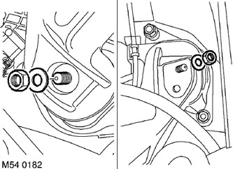
5. Remove the two engine mount nuts.
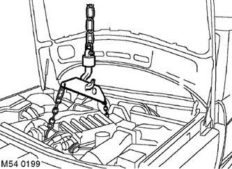
6. Install the LRT-12-216 tool onto the engine mounting tabs.
7. Attach the chain to the engine mounting brackets and tighten the chain by loading it with the weight of the engine.
8. Drain the oil from the final drive housing.
FRONT AXLE MAIN GEAR AND DIFFERENTIAL, ADJUSTMENTS, Front main gear and differential housing - oil drain and filling.
9. Remove the front propeller shaft.
DRIVE SHAFTS, REPAIR WORK, Cardan shaft - front.
10. Remove the right drive shaft inner end seal.
DRIVE SHAFTS, REPAIR WORK, Seal - drive shaft - front - right.
11. Remove the differential seal.
FRONT AXLE MAIN GEAR AND DIFFERENTIAL, REPAIR WORK, Seal - differential output shaft.
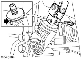
12. Remove the Torx screw from the lower steering shaft joint.
13. Turn the steering wheel to the straight-ahead position, align the marks on the steering gear shaft and remove the key from the ignition switch.
CAUTION: Do not turn the steering wheel when the intermediate shaft or universal joint is disconnected, as this will damage the slip ring and steering wheel controls.
14. Disconnect the steering shaft from the pinion shaft.
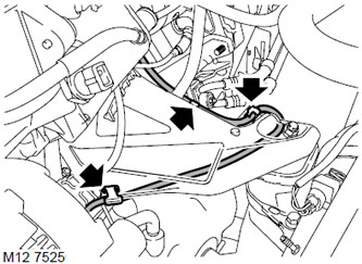
15. Release the vacuum hose from the three retainers on the left engine mount.
16. Disconnect the vacuum supply hose from the tee.
CAUTION: Always plug the fittings and holes to protect the system from dirt.
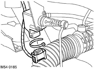
17. Mark the position of the clamps and remove the clamps securing the body position sensor cable to the subframe and the sensor itself.
18. Remove the pads from the electrical connectors of the body position sensors.
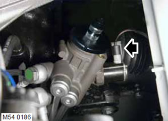
19. Remove the steering angle sensor connector block.
20. Install a container to collect the leaking working fluid.
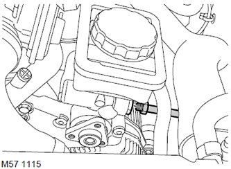
21. Loosen the union nut, disconnect the high pressure hose from the power steering pump and discard the sealing ring.
CAUTION: Before disconnecting or removing system components, make sure that the adjacent surfaces of the joints are free of dirt. Install plugs in the openings of the fittings and pipes to prevent dirt from entering the system.
22. Remove the nut securing the steering hose to the bracket.
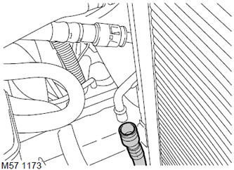
23. Loosen the fastening and disconnect the return hose from the working fluid cooler.
CAUTION: Before disconnecting or removing system components, make sure that the adjacent surfaces of the joints are free of dirt. Install plugs in the openings of the fittings and pipes to prevent dirt from entering the system.
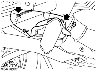
24. Remove the 2 nuts securing each anti-roll bar heat shield to the body and the 2 bolts securing each heat shield to the subframe. Remove the heat shields.
25. Support the subframe using a jack.
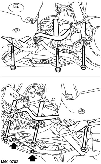
26. Remove the 6 subframe mounting screws.
27. Remove the 2 screws securing the subframe to the cross frame.
28. With the help of an assistant, lower and remove the subframe assembly.
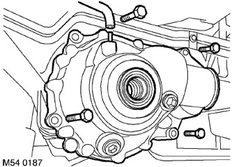
29. Disconnect the ventilation hose from the final drive housing.
30. Remove the 4 main gear mounting screws and, with the help of an assistant, remove the main gear assembly. Remove and discard the sealing ring.
Assembly
1. Clean the final drive housing and all mating surfaces.
2. Install a new sealing ring into the final drive housing and lubricate it with petroleum jelly.
3. With the help of an assistant, carefully install the final drive assembly. Tighten the mounting screws to a torque of 102 N·m.
4. Connect the ventilation hose to the final drive housing.
5. Clean the mating surfaces of the subframe and the car body.
6. Together with an assistant, install the subframe assembly.
7. Tighten the 6 subframe-to-body mounting screws to 165 Nm. Tighten the 2 rear screws another 90°.
8. Tighten the 2 subframe to cross frame mounting screws to 132.5 Nm.
9. Install the anti-roll bar heat shields and tighten the 2 bolts and nuts.
10. Lower the engine onto the supports.
11. Tighten the engine bracket mounting nuts to the supports with a tightening torque of 100 N·m.
12. Wipe the power steering hose connections.
13. Connect the power steering hose to the power steering fluid cooler.
14. Install a new sealing ring onto the hose nipple and connect the hose to the pump, tightening the nut to 25 Nm.
15. Secure the power steering hose to the bracket and tighten the retaining clip nut to a torque of 10 Nm.
16. Connect the connector to the steering angle sensor connector.
17. Connect the electrical connector blocks of the front vertical body position sensors.
18. Route the sensor cables and secure them with clamps in their original position.
19. Connect the vacuum hoses to the tee and secure the hoses in the clamps.
20. Check the alignment of the steering shaft and steering gear shaft marks and attach the steering shaft. Install the steering shaft joint screw and tighten it to 24 N·m.
21. Install the differential seal.
FRONT AXLE MAIN GEAR AND DIFFERENTIAL, REPAIR WORK, Seal - differential output shaft.
22. Install the right drive shaft seal.
DRIVE SHAFTS, REPAIR WORK, Seal - drive shaft - front - right.
23. Install the front propeller shaft.
DRIVE SHAFTS, REPAIR WORK, Cardan shaft - front.
24. Fill the final drive housing with oil to the required level.
FRONT AXLE MAIN GEAR AND DIFFERENTIAL, ADJUSTMENTS, Front main gear and differential housing - oil drain and filling.
25. Replace the protective shield.
EXTERIOR PARTS, REPAIR WORK, Engine protection - front.
26. Reinstall the air duct.
HEATING AND VENTILATION, REPAIR WORK, Air filter - air intake.
27. Install the cooling fan.
COOLING SYSTEM: Td6, REPAIR WORK, Viscous fan clutch.
28. Connect the negative terminal to the battery.
29. Remove air from the system and add working fluid to the power steering reservoir.
STEERING, ADJUSTMENTS, Power assisted steering (PAS) - bleeding.
30. Check and, if necessary, adjust the front wheel alignment.
STEERING, ADJUSTMENTS, Front wheel alignment angles - checking and adjustment.
Comments on this article