GENERAL INFORMATION, Precautions when working with electrical equipment.
Removing
1. Place the car on a lift.
2. Disconnect "mass" battery wire.
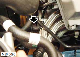
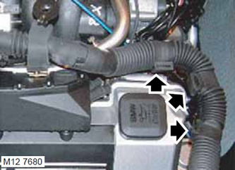
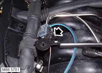
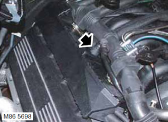
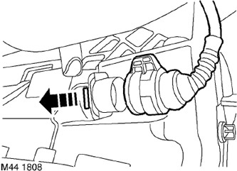
3. Remove the air hose.
ENGINE MANAGEMENT SYSTEM: V8 engine, REPAIR WORK, Hose connecting the air mass sensor to the throttle pipe.
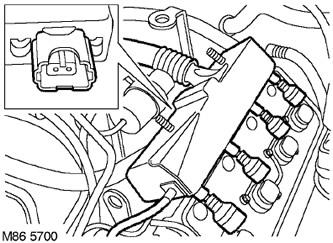
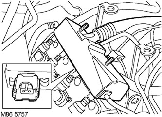
4. Remove the left cover of ignition coils.
ENGINE MANAGEMENT SYSTEM: V8 engine, REPAIR WORK, Left row ignition coil cover.
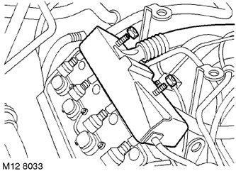
5. Remove the right cover of ignition coils.
ENGINE MANAGEMENT SYSTEM: V8 engine, REPAIR WORK, Right row ignition coil cover.
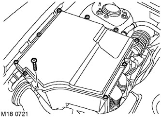
6. Remove 10 Allen screws securing the electronics box cover ("E" box) and remove the cover.

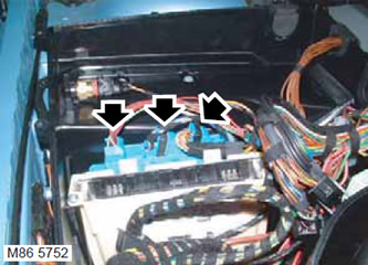
7. Disconnect 5 blocks from ECM.
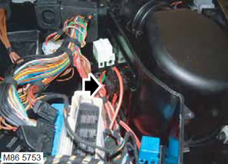
8. Disconnect 3 pads from the gearbox control unit.
9. Disconnect the engine wiring harness connector and 3 relays inside the electronics box.
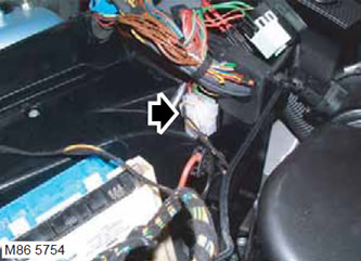
10. Disconnect the engine wiring harness block from the electronics box.
11. Turn away 2 nuts of fastening 2 "massive" engine wiring harnesses.
12. Remove the 2 insulating corrugations of the engine wiring harness from the electronics box.
13. Disconnect the pads from the ignition coils.

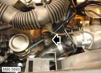
14. Disconnect the pads from the throttle body, thermostat heating element, camshaft position sensor and temperature sensor.
15. Cut off 2 plastic ties and release the engine wiring harness.
16. Disconnect blocks from electromagnetic valves of system of change of phases of gas distribution.
17. Release the solenoid valve block of the variable valve timing system from the clamp.
18. Disconnect the block from the purge valve of the fuel vapor absorber.
19. Disconnect block from the generator.
20. Release a plait of electroconducting from 4 collars.
21. Disconnect the block from the knock sensor and the camshaft position sensor.
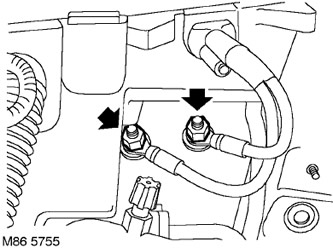
22. Turn away 2 bolts of fastening of a plait of electroconducting of fuel atomizers to a fuel rail.
23. Release the vacuum reservoir and mounting bracket from the left stud of the fuel injector wiring harness.
24. Remove the fuel pipe and bracket from the left stud of the fuel injector wiring harness.
25. Release the generator wiring harness from the 2 clamps located on the engine cover mounting bracket.
26. Disconnect blocks from fuel atomizers.
27. Release the engine wiring harness from the clamps and move it away from the valve cover.
28. Disconnect the block from the fuel vapor absorber purge solenoid valve.
29. Turn away 2 nuts of fastening of a plait of electroconducting of the engine to an inlet highway.
30. Unfasten the vacuum valve from the right stud, designed to attach the fuel injector wiring harness.
31. Remove the washer from the fuel injector harness stud.
32. Disconnect the block from the right knock sensor.
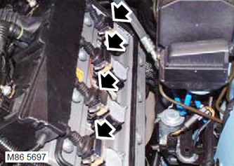
33. Disconnect the pads from the fuel injectors.
34. Position the fuel injector wiring harness.
35. Disconnect the shoe from the transmission selector switch wiring harness.
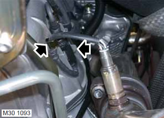
36. Remove the latch securing the wiring of the left oxygen sensor to the gearbox housing.
37. Disconnect the block from the engine wiring harness.
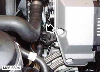
38. Disconnect the shoe from the crankshaft position sensor.
39. Release the crankshaft position sensor wire from the clamp on the right side of the gearbox.
40. Loosen the wire clamp of the upper oxygen sensor, remove the block from the mount and disconnect it.
41. Take out a tube of ventilation of a transmission from a collar located from above.
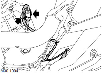
42. Remove the wires of the lower oxygen sensors from the clamp, disconnect the block.
43. Disconnect the block from the gearbox.
44. Note the location of the wiring harness and remove the harness.
Installation
1. Correctly position the wiring harness on the engine.
2. Attach a block of wires to a transmission.
3. Attach the block to the lower oxygen sensors and secure it with a clamp.
4. Fix a tube of ventilation of a transmission in a collar located from above.
5. Attach the block to the upper oxygen sensors and secure it with a clamp.
6. Secure the crankshaft position sensor wire with a clamp on the right side of the gearbox.
7. Attach the shoe to the crankshaft position sensor.
8. Connect the block to the engine wiring harness.
9. Establish a wire of the left gauge of oxygen and fix it by means of a collar.
10. Install and secure the transmission selector switch harness and attach the block.
11. Position the fuel injector harness.
12. Attach the fuel injector harness connector.
13. Install the washer on the fuel injector harness stud.
14. Install the valve on the right fuel injector harness stud.
15. Establish 2 nuts of fastening of a plait of fuel atomizers to an inlet highway.
16. Attach the block to the fuel vapor absorber valve.
17. Install and secure the engine wiring harness to the bracket with a clamp.
18. Attach the fuel injector harness connector.
19. Attach the alternator harness to the 2 clamps located on the engine cover mounting bracket.
20. Attach the fuel pipe and mounting bracket to the left injector harness stud.
21. Attach the vacuum reservoir and mounting bracket to the left stud of the injector wiring harness.
22. Establish 2 nuts of fastening of a plait of fuel atomizers to an inlet highway and tighten them.
23. Attach the shoe to the knock sensor.
24. Attach the shoe to the camshaft position sensor.
25. Secure the generator wiring harness with 4 clamps.
26. Connect the block to the generator connector.
27. Attach the block to the valve of the fuel vapor absorber.
28. Secure the block of the wiring harness for the variable valve timing system with a retainer.
29. Attach the shoe to the valve body.
30. Install new plastic clamps and secure the harness.
31. Attach the block to the camshaft position sensor.
32. Attach the shoe to the throttle body.
33. Connect the block to the generator connector.
34. Attach the block to the coolant temperature sensor.
35. Attach the 2 insulating corrugations of the engine wiring harness to the electronics box.
36. Position 2 correctly "massive" engine wires, install the nuts and tighten them.
37. Attach the block of the engine wiring harness to the electronics box.
38. Mount the 3 relays on the bracket in the electronics box.
39. Attach the block of the engine wiring harness to the electronics box.
40. Attach 3 pads to the transmission ECU.
41. Attach 5 pads to the ECM.
42. Install the electronics box cover and tighten the hexagon head screws.
43. Install the left cover of the ignition coils.
ENGINE MANAGEMENT SYSTEM: V8 engine, REPAIR WORK, Right row ignition coil cover.
44. Establish the right cover of coils of ignition.
ENGINE MANAGEMENT SYSTEM: V8 engine, REPAIR WORK, Left row ignition coil cover.
45. Replace the air hose.
ENGINE MANAGEMENT SYSTEM: V8 engine, REPAIR WORK, Hose connecting the air mass sensor to the throttle pipe.
46. Connect "mass" battery wire.
Comments on this article