Contents: Dismantling ⇩ Installation ⇩
Dismantling
1. Follow all safety rules when working with the airbag system.
GENERAL INFORMATION, Rules for working with airbags and seat belt pretensioners.
2. Remove the carpet.
3. Remove the engine soundproofing cover.
ENGINE - Td4, Inlet and outlet camshafts, Engine soundproofing casing, models produced before May 2002.
4. Remove the windshield washer reservoir.
WINDSHIELD WIPERS AND WASHERS, REPAIR WORK, Reservoir - washer.
5. Pull the wiring harness and washer tubes into the engine compartment.
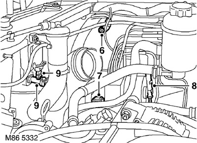
6. Unscrew the nut and release the ground collector from the inner part of the right wing.
7. Disconnect the connector from the ABS modulator.
8. Disconnect the connector from the right ABS sensor and remove the harness from the retainer.
9. Disconnect the 2 connectors from the right headlight and the headlight adjustment motor.
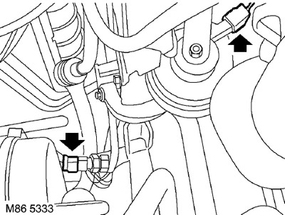
10. Disconnect the connectors from the horn, air conditioning pressure sensor and air conditioning compressor.
11. Disconnect the terminal block from the holder in the engine compartment.
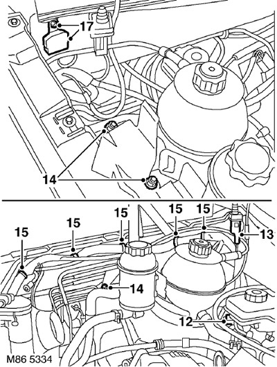
12. Disconnect the connector from the brake fluid level sensor.
13. Disconnect the connector from the hood switch.
14. Remove the bolt and 2 nuts securing the coolant system and hydraulic booster reservoir bracket and place them aside.
15. Loosen the 5 clamps holding the harness.
16. Disconnect the washer tubes from the wiring harness and place them to the side.
17. Unscrew the nut securing the ground manifold to the engine compartment bulkhead and remove the manifold.
[The original text was published on the website: www.lrman.ru]
18. Using assistance, pull the wiring harness through the engine compartment bulkhead into the vehicle's interior.
19. Remove the battery tray.
ENGINE STARTING AND BATTERY CHARGING SYSTEM, REPAIR WORK, Support tray - battery.
20. Disconnect the 3 strap clamps and remove the hood lock control cable from the wiring harness.
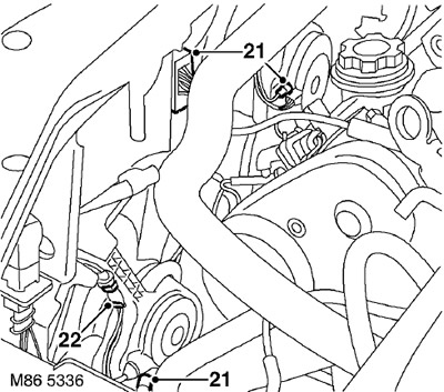
21. Disconnect the connector from the cooling fan control module and 2 connectors from the cooling fan motors.
22. Loosen the 4 clamps securing the wiring harness to the cooling system fans and remove the harness.
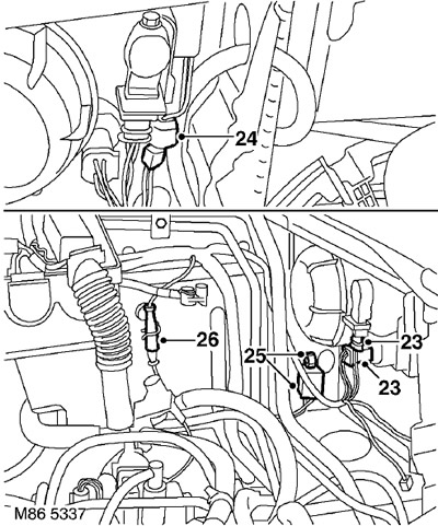
23. Disconnect the 2 connectors from the left headlight and the headlight adjustment motor.
24. Disconnect the connector from the wiring harness.
25. Unscrew the left ground manifold mounting nut and remove the manifold.
26. Disconnect the connector block from the left ABS sensor.
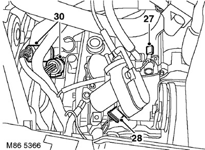
27. Disconnect the connector from the starter.
28. Models with cruise control system: Disconnect the connector from the cruise control pump.
29. Loosen the 5 clamps holding the harness.
30. Disconnect the 2 connectors connecting the engine wiring harness to the main harness.
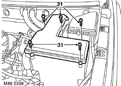
31. Unscrew the 5 screws (Allen type) securing the cover of the electronic unit box ("E" box).
32. Remove the cover of the electronic unit box ("E" box).
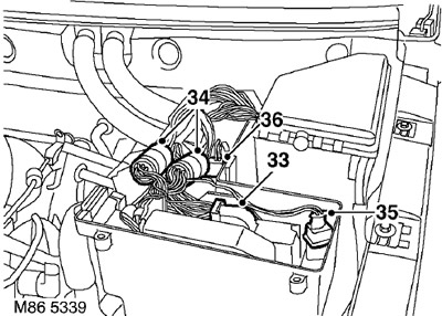
33. Automatic transmission models only: Disconnect the connector from the automatic transmission ECU.
34. Disconnect the 2 connectors connecting the engine wiring harness to the main harness.
35. Disconnect the connector to the temperature sensor located inside the electronic unit box ("E" box).
36. Disconnect the connector from the electronic unit box cooling fan ("E" box).
37. Remove the fuse box cover.
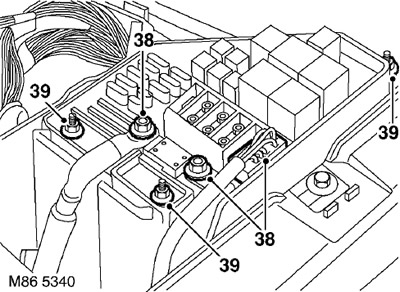
38. Unscrew the 2 bolts securing the connection from the battery to the fuse box and disconnect the block from the fuse box.
39. Unscrew the 3 nuts securing the fuse box to the bracket.
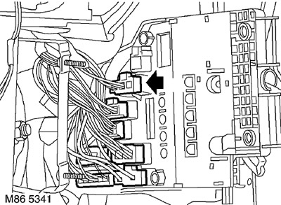
40. Disconnect the 6 connectors from the back of the fuse box.
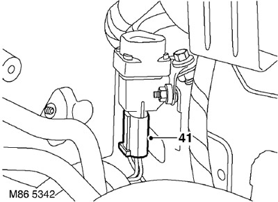
41. Disconnect the connector from the inertia switch.
42. Disconnect the 2 wiring harness fasteners on the left side of the engine compartment.
43. Remove the air intake panel.
HEATING AND VENTILATION, REPAIR WORKS, Air intake box.
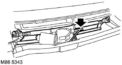
44. Disconnect the connector from the windshield wiper motor and pull it into the engine compartment.
45. Using assistance, route the main wiring harness into the vehicle's interior.
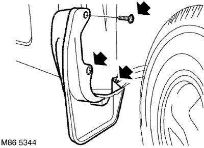
46. Unscrew the 6 screws securing the front mudguards and remove the mudguards.
47. Unfasten the rear edges of the front wheel arch protection.
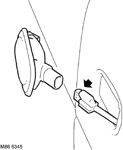
48. Remove the side turn signal lamps, disconnect the connectors and remove the lamps.
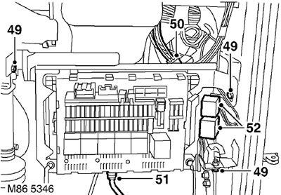
49. Remove the 3 bolts from the passenger compartment fuse box and slide the fuse box forward.
50. Loosen and disconnect the connector on the right side of the "A" pillar.
51. Disconnect the coaxial cable.
52. Remove the relay from the fuse box bracket.
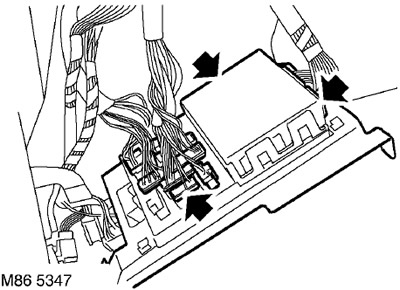
53. Release the fuse box, disconnect the 11 connectors and remove the fuse box.
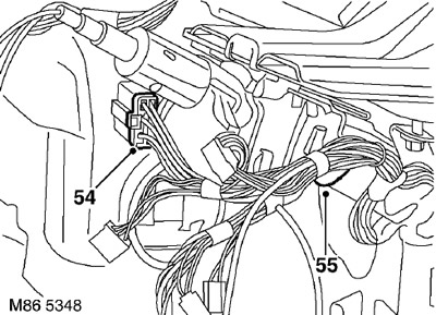
54. Disconnect the connector from the steering column switches.
55. Disconnect the harness retainer from the steering column.
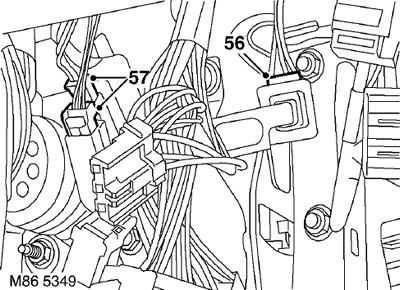
56. Disconnect the throttle position sensor connector.
57. Disconnect the connector from the brake light switch and brake pedal position sensor.
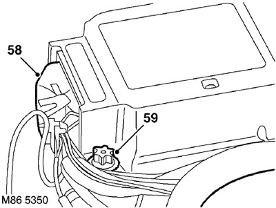
58. Disconnect the connector from the airbag module.
59. Loosen the airbag ECU mounting bolt and disconnect the ground wire.
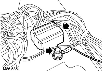
60. Unscrew the nut from the ground collector and remove the collector from the tunnel.
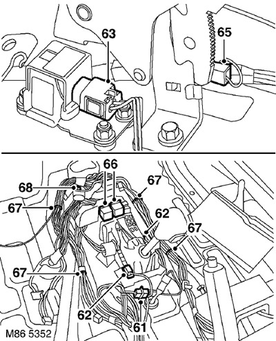
61. Disconnect the connector from the heated oxygen sensor.
62. Automatic transmission models only: Disconnect the connector from the transmission selector switch.
63. Disconnect the accelerometer connector.
64. Manual transmission models only: Disconnect the connector from the hill descent control switch located on the transmission control lever.
65. Disconnect the connector from the parking brake switch connector.
66. Remove the 2 relays from the bracket and remove the bracket.
67. Remove the 4 clamps securing the harness to the air box.
68. Unscrew the nut from the rear heater box and remove the box.
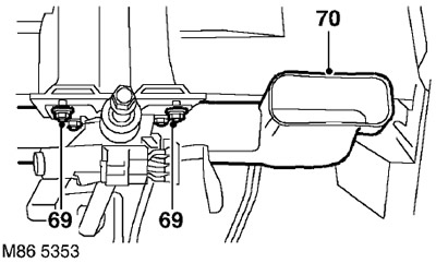
69. Unscrew the 4 nuts securing the steering column to the bracket and lower the column.
70. Remove the air duct that distributes the air flow to the passenger's face level, providing access to the main wiring harness clamps.
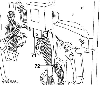
71. Disconnect the connector from the window lifter control unit.
72. Unscrew the nut securing the ground manifold to the right pillar "A" and remove the manifold.
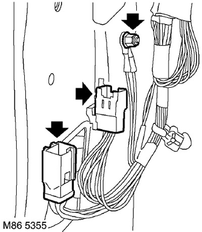
73. Remove the connector and the ground collector at the bottom of the left A-pillar.
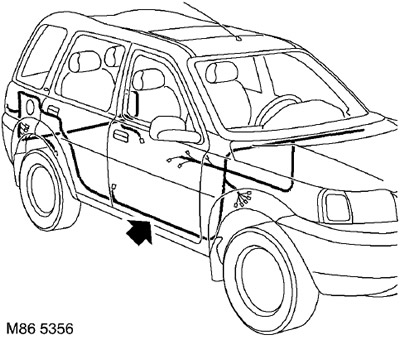
74. Release all wiring harness clamps from the vehicle interior.
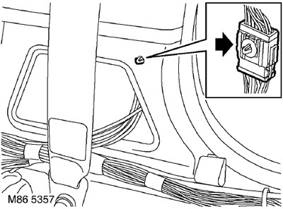
75. Loosen and disconnect the shoes on the "B/C" pillar.
76. Remove the cargo area carpet.
INTERIOR TRIM DETAILS, REPAIR WORK, Luggage compartment floor covering.
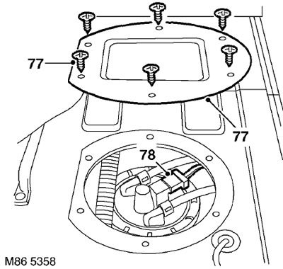
77. Unscrew the 6 bolts of the fuel pump access hatch cover and remove it.
78. Disconnect the connector from the fuel pump.
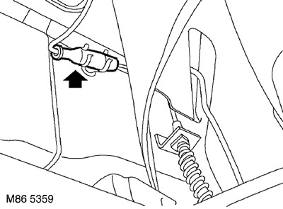
79. Loosen the harnesses of both ABS sensors and disconnect the pads.
80. Pull the harness inside the car.
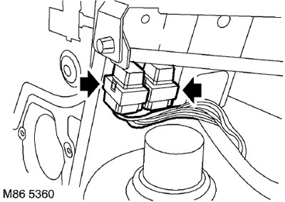
81. Loosen and disconnect the rear window relay and wiper/washer relay.
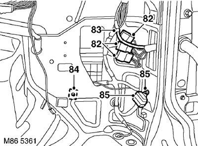
82. Disconnect the 3 connectors from the cargo door wiring harness.
83. Disconnect the cargo door glass washer pipe.
84. Disconnect the connector block from the trailer electrical equipment.
85. Unscrew the rear ground manifold nut and release the manifold.
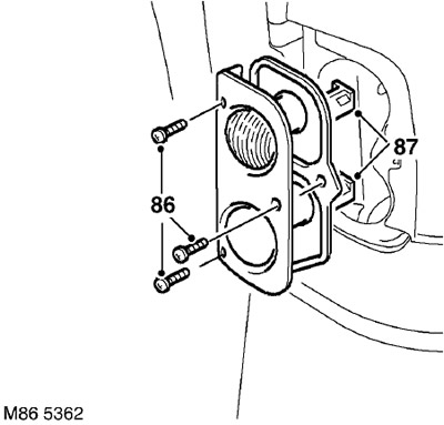
86. Unscrew the 3 screws securing the right rear light to the body.
87. Disconnect the pads and remove the light.
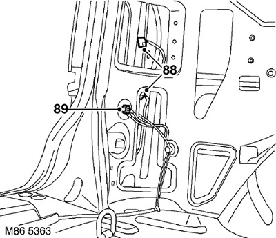
88. Disconnect the rear left light connectors.
89. Unscrew the nut from the rear left ground manifold and remove the manifold.
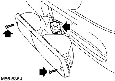
90. Unscrew the 4 screws of the rear bumper lights, remove the lights and disconnect the pads.
91. Loosen the harness clamps and route the harness into the cargo area.
92. Loosen the clamps securing the main harness and pull the harness into the vehicle interior.
93. Remove the main wiring harness.
Installation
1. Place the main wiring harness into the vehicle.
2. Place the back part of the harness and secure with clamps.
3. Route the harness to the lights in the rear bumper, secure it with clamps and seals.
4. Attach the pads to the lights in the rear bumper, install the lights and secure with screws.
5. Install the left rear ground manifold and secure with the nut.
6. Connect the connector to the left rear light.
7. Position the right rear light and attach the connector.
8. Install the right rear light and secure it with screws.
9. Install the right rear ground manifold and secure with the nut.
10. Connect the connector to the trailer electrical equipment socket.
11. Connect the rear window washer hose.
12. Connect the cargo door connector block.
13. Connect and install the rear window and wiper/washer relay.
14. Place the wiring harness in the cargo area.
15. Connect both ABS sensor connectors and secure the harness seals.
16. Connect the connector to the fuel pump.
17. Replace the fuel pump access cover and secure it with screws.
18. Lay down the luggage compartment carpet.
INTERIOR TRIM DETAILS, REPAIR WORK, Luggage compartment floor covering.
19. Attach the shoe to the base of the "B/C" pillar.
20. Install all harness mounting clamps inside the vehicle.
21. Install and secure the ground collector to the bottom of the left A-pillar.
22. Install and secure the ground collector to the bottom of the right A-pillar.
23. Connect the connector to the window lift control unit.
24. Install a box supplying air at the level of the passengers" faces.
25. Attach the steering column to the bracket and secure using nuts.
26. Install the rear heater box and secure it using the nut.
27. Secure the harness to the rear heater box using clamps.
28. Position the mounting bracket and secure the relay.
29. Connect the shoe to the parking brake switch.
30. Manual transmission models only: Connect the shoe to the hill descent control switch located on the transmission lever.
31. Connect the connector to the accelerometer.
32. Automatic transmission models only: Disconnect the connector to the transmission selector switch.
33. Connect the connector to the heated oxygen sensor.
34. Install the ground collector onto the tunnel and secure it using the nut.
35. Install the negative wire to the airbag ECU and secure it using the bolt.
36. Connect the connector to the airbag module connector.
37. Connect the connector to the brake light and brake pedal position switch.
38. Connect the connector to the throttle position sensor.
39. Install the harness clamp onto the steering column.
40. Connect the connector to the steering column switch.
41. Install the fuse box and connect the connectors.
42. Install the relay into the fuse box bracket.
43. Connect the coaxial cable.
44. Install and secure the connector block to the right "A" pillar.
45. Install the fuse box and secure it with bolts.
46. Position the turn signal lights, attach the pads and secure them to the wing.
47. Secure the rear edges of the front wheel arch protection.
48. Install the front mudguards and secure them with screws.
49. Using assistance, pull the harness through the engine compartment bulkhead into the engine compartment.
50. Place the harness next to the wiper motor and connect the connector.
51. Reinstall the air intake panel.
HEATING AND VENTILATION, REPAIR WORKS, Air intake box.
52. Place the harness along the left side of the engine compartment and secure.
53. Connect the block to the inertia switch.
54. Connect the connectors to the back of the fuse box.
55. Install the nuts securing the fuse box to the bracket.
56. Establish a connection to the battery and the pads to the fuse box.
57. Replace the fuse box cover.
58. Connect the connector to the E-box cooling fan.
59. Connect the connector to the temperature sensor located inside the electronic unit box.
60. Connect the engine wiring harness connector to the main harness.
61. Automatic transmission models only: Connect the connector to the automatic transmission ECU.
62. Install the electronics box cover and tighten the Allen head screws.
63. Connect the engine wiring harness connector to the main harness.
64. Install the clamps holding the harness.
65. Models with cruise control system installed: Connect the connector to the vacuum pump.
66. Connect the shoe to the starter.
67. Connect the connector to the left ABS sensor connector.
68. Install the left ground manifold and secure with the nut.
69. Connect the connector to the wiring harness.
70. Connect the pads to the left headlight and headlight adjustment motor.
71. Secure the harness using the cooling fan clamps.
72. Connect the pads to the cooling system fan control unit and to the cooling system electric motors.
73. Place the hood lock control cable into the wiring harness and secure with cable ties.
74. Reinstall the battery tray.
ENGINE STARTING AND BATTERY CHARGING SYSTEM, REPAIR WORK, Support tray - battery.
75. With the help of a partner, pull the harness through the bulkhead into the engine compartment.
76. Install the ground collector on the engine compartment bulkhead and secure it with a nut.
77. Position the windshield washer tube in the harness.
78. Install the clamps holding the harness.
79. Install the coolant reservoir and hydraulic booster mounting bracket and secure using the bolt and nuts.
80. Connect the wiring harness to the hood switch.
81. Connect the connector to the low brake fluid level sensor.
82. Connect the terminal block to the manifold in the engine compartment.
83. Connect the connectors to the horn connector, the air conditioning pressure sensor and the air conditioning compressor.
84. Connect the pads to the right headlight and headlight adjustment motor.
85. Attach the connector to the right ABS sensor and secure using clamps.
86. Connect the connector to the ABS modulator connector.
87. Install the ground collector on the inside of the right wing and secure it using the nut.
88. Place the harness next to the windshield washer reservoir.
89. Install the windshield washer reservoir.
WINDSHIELD WIPERS AND WASHERS, REPAIR WORK, Reservoir - washer.
90. Reinstall the engine soundproofing cover.
ENGINE - Td4, Inlet and outlet camshafts, Engine soundproofing casing, models produced before May 2002.
91. Put the carpet back in place.
Comments on this article