Contents: Removal ⇩ Installation ⇩
Removal
1.
CAUTION: Do not work on a vehicle supported only by a jack. Be sure to support the vehicle securely.
Raise and support the vehicle.
2. Remove the engine protection shield. For more information, refer to Engine Protection (76.10.50)
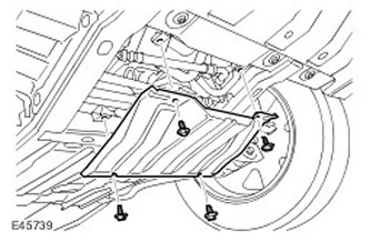
3. Remove the radiator access panel. Remove 4 bolts.
4. Remove the engine cover. For more information, refer to Engine Cover - 4.4L (12.30.50)
5. Remove the battery. For more information, refer to Battery (86.15.01)
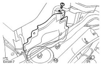
6. Remove the upper engine compartment heat shield.
- Remove the screw.
- Release the 2 mounting clips.
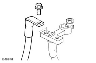
7. Remove the main power supply cable from the fuse box in the engine compartment. Remove the bolt.
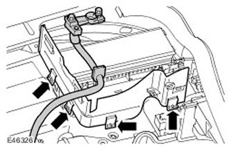
8. Remove the side wall of the battery compartment.
- Release the positive battery cable and grommet.
- Release the 4 clamps.
9. Remove the engine wiring harness from the battery compartment. Disconnect the two electrical connectors of the engine wiring harness.
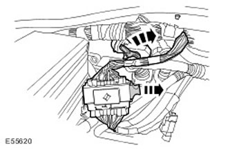
10. Release the 2 clips on the wiring harness protective cover.
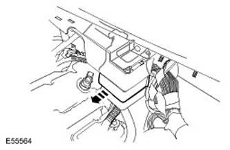
11. Remove the fuel supply line.
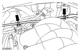
12. Remove the engine wiring harness from the support bracket. Remove the 2 bolts.
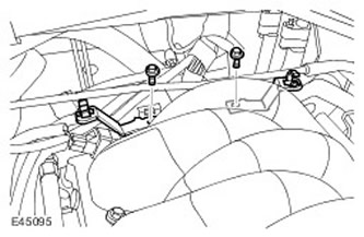
13. Disconnect the manifold absolute pressure (MAP) sensor electrical connector.
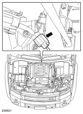
14. Disconnect the throttle body electrical connector. Release the 3 clamps.
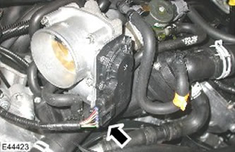
15. Disconnect the knock sensor (KS) electrical connector.
16. Disconnect the mass air flow (MAF) sensor electrical connector.
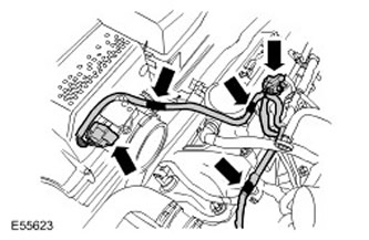
17. Remove the direct ignition coil cover (coil in block with spark plug).
- Release the 2 clamps.
- Repeat the above procedure on the other side.
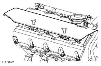
18. Disconnect the variable valve timing (VCT) solenoid electrical connector. Repeat the above procedure on the right side.
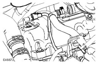
19. Disconnect the 4 electrical connectors from the left injectors.
- Release the 2 clamps.
- Repeat the above procedure on the right side.
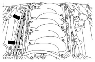
20. Disconnect the connectors of the 4 left direct ignition coils (coils in the block with spark plugs).
- Release the 2 clamps.
- Repeat the above procedure on the right side.
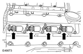
21. Disconnect the engine coolant temperature (ECT) sensor electrical connector.
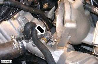
22. Disconnect the fuel temperature sensor electrical connector.
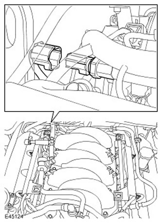
23. Disconnect the camshaft position (CMP) sensor electrical connector. Repeat the above procedure on the right side.
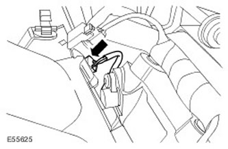
24. Disconnect the EGR valve electrical connector.
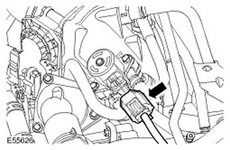
25. Disconnect the ground connector from the cylinder head. Release the 3 clamps.
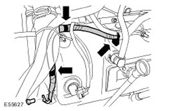
26. Disconnect the cooling fan electrical connector.
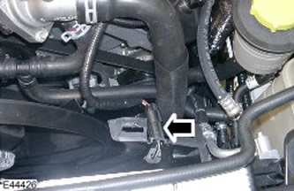
27. Disconnect the air conditioning compressor electrical connector.
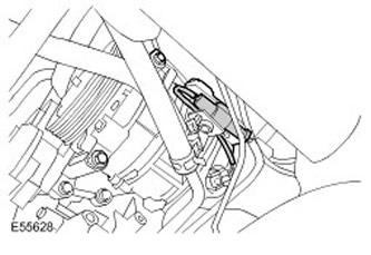
28. Remove the 4 A/C wire harness support clamps.
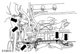
29. Disconnect the crankshaft position sensor (CSP) electrical connector.
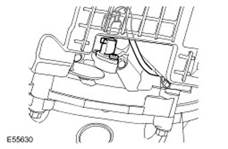
30. Remove the front wheel.
31. Remove the left fender mudguard. For more information, refer to Fender Mudguard (76.10.48)
32. Remove the left front fender splash guard.
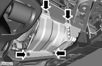
33. For ease of access, remove the heat shield of the upper suspension arm and brake system pipe.
- Remove 3 bolts.
- Unscrew 3 nuts.
- Repeat the above procedure on the other side.
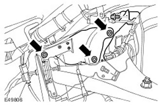
34. Release the accessory drive belt. Turn the tensioner assembly counterclockwise.
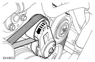
35. Release the transmission fluid cooler tube clamps.
36. Remove the power steering pump and support bracket. Remove the 3 bolts.
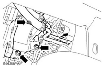
37. Release the air conditioning compressor mount, move it to the side and tie it up. Remove the 3 bolts.
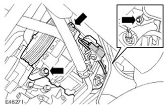
38. Remove the air conditioning compressor support bracket. Remove 2 bolts.
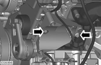
39. Disconnect the starter electrical connector.
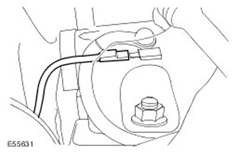
40. Disconnect the engine oil temperature and pressure sensors.

41. Disconnect the generator electrical connector.
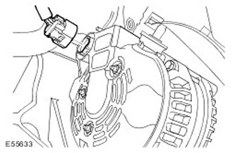
42. Release the 4 generator wiring harness retaining clips.
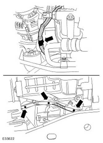
43. Remove the purge valve from the support bracket.
- Disconnect the electrical connector.
- Remove the bolt.
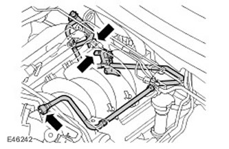
44. Disconnect the front left HO2S sensor and release the clamp.
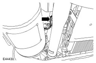
45. Disconnect the right HO2S sensor and release the clamp.
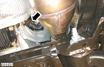
46. Remove the engine wiring harness.
Installation
1. Install the engine wiring harness.
2. Connect the heated oxygen sensor electrical connectors. Carefully tighten the clamps.
3. Install the purge valve.
- Secure the wiring harness with a clamp.
- Tighten the bolt (tightening torque 6 Nm).
- Connect and secure the electrical connector.
5. Connect the engine oil temperature and pressure sensors.
6. Connect the generator electrical connector. Secure the clamps.
7. Connect the crankshaft position (CKP) sensor electrical connector.
8. Connect the electrical connector of the air compressor.
9. Install the air conditioning compressor support bracket. Tighten the bolts. (tightening torque 25 Nm).
10. Install the power steering pump and support bracket.
- Tighten the bolts (tightening torque 25 Nm).
- Tighten the bolts (tightening torque 25 Nm).
12. Install the air conditioning compressor. Tighten the bolts. (tightening torque 25 Nm).
13. Install the accessory drive belt.
14. Install the upper control arm heat shield and brake line. Tighten the nuts and bolts to 10 Nm.
15. Install the fender splash guard. For more information, refer to Fender Splash Guard (76.10.48)
16. Install the mudguard.
17. Install the front wheel. Tighten the nuts. (tightening torque 115 Nm).
18. Connect the cooling fan electrical connector.
19. Connect the ground connector to the cylinder head. Tighten the bolt. (tightening torque 10 Nm).
20. Connect the EGR valve electrical connector.
21. Install the camshaft position sensors (CMP) for both camshafts.
22. Connect the fuel pressure sensor electrical connector.
23. Connect the MAP sensor electrical connector.
24. Install KS.
25. Connect the ECT sensor electrical connector.
26. Connect the electrical connectors of the direct ignition coils.
- Install the clamps.
- Repeat the above procedure on the other side.
- Install the clamps.
- Repeat the above procedure on the other side.
29. Install the direct ignition coil cover (coil in block with spark plug).
- Secure the clamps.
- Repeat the above procedure on the other side.
31. Connect the throttle body electrical connector. Secure the clamps.
32. Connect the MAP sensor electrical connector.
33. Install the wiring harness support bracket. Tighten the bolt. (tightening torque 10 Nm).
34. Connect the engine wiring harness.
- Install the clamps onto the wiring harness protective cover.
- Connect and secure the electrical connectors.
- Secure the clamps.
- Install the positive battery cable and grommet.
37. Install the upper engine heat shield.
- Secure the clamps.
- Tighten the screw.
39. Install the engine cover. For more information, refer to Engine Cover - 4.4L (12.30.50)
40. Install the radiator access panel. Tighten the bolt. (tightening torque 10 Nm).
41. Install the engine protection screen. For more information, refer to Engine Protection (76.10.50)
Comments on this article