Contents: Communication networks (mOST…⇩ Communication networks (CAN bus) ⇩ Communication networks (CAN bus) ⇩ Controller Area Network (CAN) ⇩ Multimedia bus (MOST) ⇩ Video Interface (GVIF) ⇩ Local Bus LIN ⇩ Diagnostic connector ⇩
Communication networks (mOST multimedia bus)
NOTE: D - High Speed CAN Bus, P - MOST
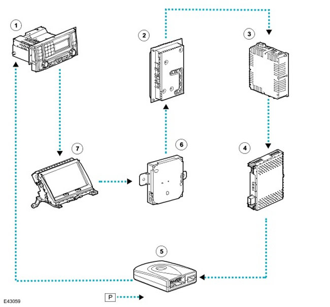
| Item name | Spare part catalog number | Description |
| 1 | - | Instrument panel |
| 2 | - | HarmanKardon Logic 7 Amplifier |
| 3 | - | Infotainment system module for rear-seat passengers |
| 4 | - | Automatic DVD changer |
| 5 | - | Harman Kardon Amplifier |
| 6 | - | Transceiver |
| 7 | - | Traffic Message Channel (TMC) |
| 8 | - | Touch Screen (TSD) |
| 9 | - | TV tuner |
| 10 | - | Integrated Head Unit (IHU) |
Communication networks (CAN bus)
NOTE: D - High Speed CAN Bus, N - Medium Speed CAN Bus, O - Local Data Bus LIN
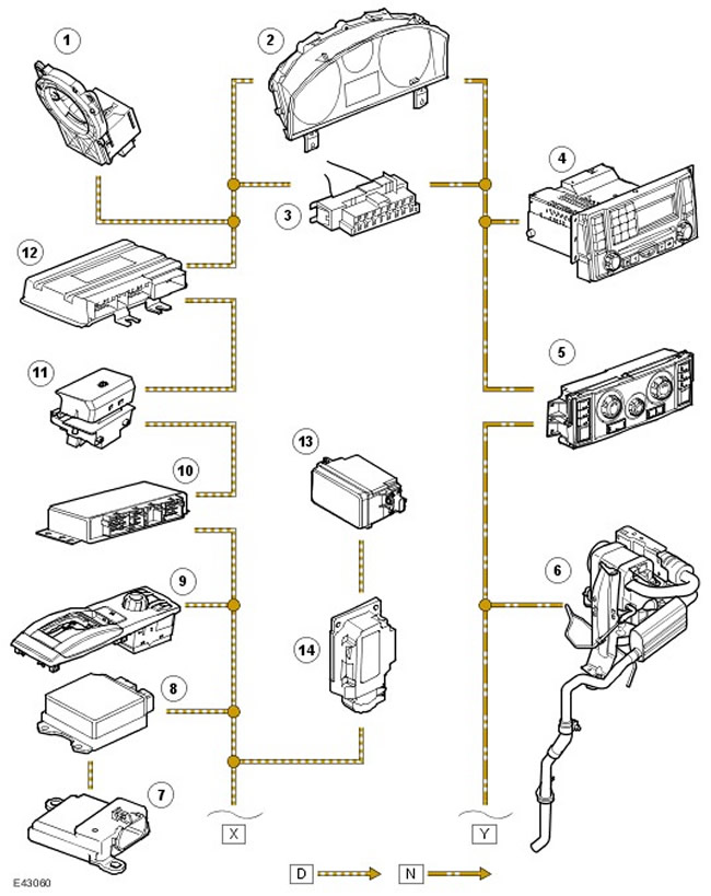
| Item name | Spare part catalog number | Description |
| 1 | - | Steering wheel angle sensor |
| 2 | - | Instrument panel |
| 3 | - | Diagnostic connector |
| 4 | - | Integrated Head Unit (IHU) or Head Unit |
| 5 | - | Control panel for heating and ventilation of the passenger compartment |
| 6 | - | Fuel fired heater |
| 7 | - | Passenger presence sensor (for US market vehicles only) |
| 8 | - | Passive safety system controller |
| 9 | - | TERRAIN RESPONSE™ System Controller |
| 10 | - | Rear axle differential controller |
| 11 | - | Parking brake controller |
| 12 | - | Air suspension controller |
Communication networks (CAN bus)
NOTE: D - High Speed CAN Bus, N - Medium Speed CAN Bus, O - Local Data Bus LIN
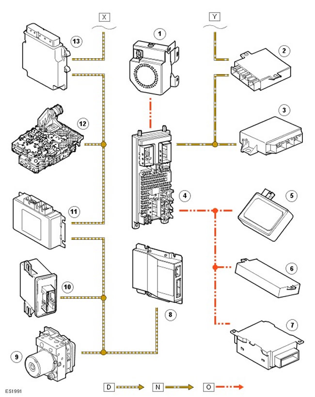
| Item name | Spare part catalog number | Description |
| 1 | - | Engine control unit |
| 2 | - | Tire Pressure Monitoring System Controller |
| 3 | - | Parking Distance Control (PDC) |
| 4 | - | Central Junction Box (CJB). |
| 5 | - | Rain sensor |
| 6 | - | Memory controller |
| 7 | - | Sunroof Controller |
| 8 | - | Self-powered alarm siren (BBUS) |
| 9 | - | ABS controller |
| 10 | - | Adaptive headlights (AFS) |
| 11 | - | Transfer case controller |
| 12 | - | Gearbox controller |
There are several types of data buses in the vehicle's electrical system that carry commands and other information between electronic control units. The configuration of the buses depends on the model and trim level of the specific vehicle.
The following are the types of multiplex buses for on-board equipment:
- High-speed Controller Area Network (CAN) bus
- Medium speed CAN bus
- Multimedia bus (MOST)
- Video Interface (GVIF)
- Local Bus LIN
- Local bus of the security system SLIN
| Tire | Data transfer rate | Protocol |
| High-speed CAN bus | 500 kbps | 11898 |
| Medium speed CAN bus | 125 kbps | 11898 |
| MOST | 24 Mbps | MOST merger |
| GVIF | 1.95 Gbps | Original Sony development |
| LIN bus | 9.6 kbps | LIN Consortium |
Controller Area Network (CAN)
The CAN bus is a high-speed data link over which ECUs automatically transmit information across the bus every few microseconds. The speed of information transfer on other buses is much lower. These buses are primarily "event-based", i.e. they only transmit messages in response to requests from the ECU or when the state of switches and sensors changes.
Structurally, the CAN bus is two-wire, made in the form of a so-called "twisted pair", and all other buses are single-wire. The wiring can be repaired using crimp connections. The length of the unwound CAN bus should not exceed 40 mm.
The vehicle uses two CAN buses:
- Medium speed tire
- High speed tire
- Integrated Head Unit (IHU) or Standard Head Unit
- Control panel for heating and ventilation of the passenger compartment
- Fuel fired heater
- Parking assistance system
- Tire Pressure Monitoring System Controller
- Central switching unit
- Steering wheel angle sensor
- Air suspension
- Electric parking brake
- Rear axle differential controller
- TERRAIN RESPONSE™ System Controller
- Passive safety system controller
- Electronic engine control unit
- Gearbox controller
- Adaptive Headlight Controller
- Anti-lock Brake System (ABS) Controller
Electronic units can be connected by a ribbon cable (cAN input/output) or by means of branches from the main bus. In the first case, a controller failure leads to the failure of the entire network at that point. In the second case, only the faulty controller fails, and the rest of the network remains operational.
Multimedia bus (MOST)
The MOST fiber optic bus is designed to transmit data within the infotainment system. The MOST fiber optic bus provides a daisy chain connection between devices, each of which has a MOST input and output connector.
MOST is a synchronous network. The master device of the network sets the time, and all other devices operate according to the synchronizing pulses of this timer. For a MOST network, the master device is the integrated audio head unit (IHU).
The MOST network has the following features:
- ease of connections;
- reduced number of wires;
- support for synchronous and asynchronous data transfer protocols;
- simultaneous support for up to 64 devices;
- high data transfer rate.
- The minimum bending radius of the tire is 25 mm.
- It is not recommended to look at the end of the connector of a working bus.
- MOST tires cannot be repaired. A "bypass" wiring harness can be ordered to replace damaged tires.
Data taken from the website (LRMAN.RU)
Video Interface (GVIF)
The GVIF bus is a development by Sony, designed to transmit video information from the transmitter to the display. In this case, it is used only to transmit video signals from the navigation system computer to the touch screen display (TSD).
Local Bus LIN
There are two Local Area Network (LIN) buses in the vehicle. One of them connects the rain sensor, sunroof and seat memory to the central switching unit, and the other connects the BbUs (self-powered alarm siren) also with a central switching unit.
The LIN bus configuration is based on the principle "Master/Slave" (i.e. the network has a master and slave devices). The master stores a "schedule", i.e. a list of all LIN data frames or packets in order, sorted by time and number of times sent in a given cycle. The master sends "headers" on the bus, which allow slaves to establish their order of transmission of the frame. The slave then fills the space after the header with the frame contents. The frame identifiers come from the LIN specification and are grouped by frame size in bytes. All nodes connected to the LIN bus are optional, so there is a different schedule for each reordering and the master switches between these devices, depending on the data stored in the vehicle configuration file. The CJB also acts as a bi-directional gateway between the medium speed CAN bus and the LIN bus, allowing signals to be exchanged between the two buses.
The bus is single-wire and operates at 9.6 kbps. The data transmission protocol is defined by the LIN consortium.
Diagnostic connector
The diagnostic connector allows information to be transferred between the vehicle's electronic units and the T4 diagnostic device via a high- or medium-speed CAN bus, as well as indirectly via the instrument cluster. The diagnostic connector is located at the bottom of the driver's side control panel trim, under the steering column.
Comments on this article