Contents: Removal ⇩ Installation ⇩
Removal
All cars
1.
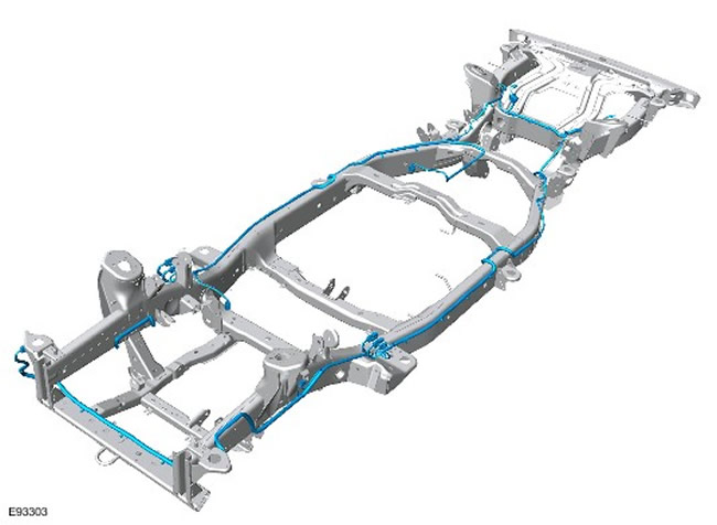
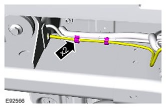
NOTE: All wiring harness terminals can be accessed with the body mounted to the frame. The illustration shows the wiring harness routing.
Routing the frame wiring harness.
2. Open the trunk door.
3. Remove the spare wheel with the tire.
4.
CAUTION: Never work on or under a vehicle that is supported solely by a jack. Always support the vehicle securely.
Raise the vehicle and support it on jack stands.
5. Disconnect the battery ground cable. For more information, refer to Specification.
6. Remove the wheels and tires.
7. Remove the bumper cover. For more information, refer to Front Bumper Cover (76.22.72)
8. Remove the right fender splash guard. For more information, refer to Fender Splash Guard (76.10.48)
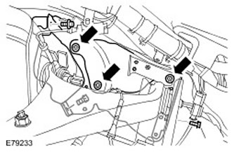
9. To gain access, remove the upper arm and brake line heat shields.
- Unscrew the three nuts.
- Remove 3 bolts.
10. Right Front: Remove the suspension height sensor. For more information, refer to Suspension Height Sensor (60.36.01)
11. Right side: Disconnect the frame wiring harness from the frame.
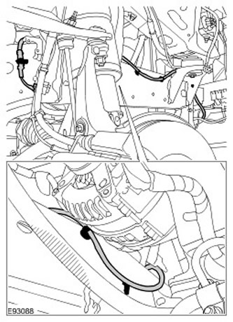
12. Disconnect the electrical connector from the right front air suspension solenoid valve. Disconnect the air suspension air line.
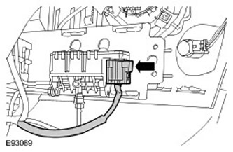
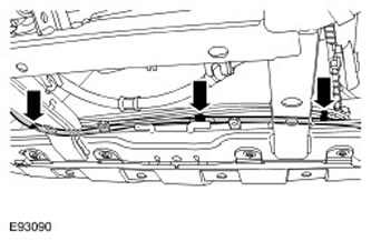
13. Disconnect the frame wiring harness from the front frame cross member.
- Release the 2 air suspension lines.
- Release the three clamps.
14. Move the frame wiring harness to the left front wheel well.
15. Remove the left wing splash guard. For more information, refer to Wing Splash Guard (76.10.48)
16. Remove the left front wheel and tire support.

17. Left front side: Disconnect the electrical connector of the height sensor. Release the clamp.
18. Disconnect the ground wire from the wheel arch ground contact. Release the 2 clamps.
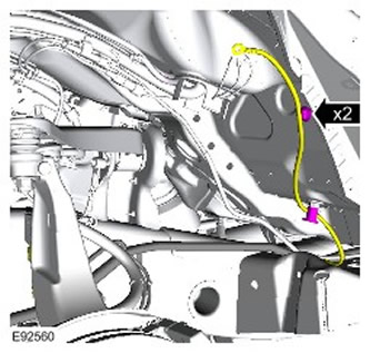
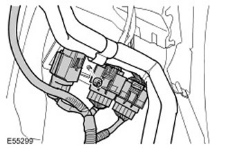
19. Disconnect the 3 electrical connectors from the frame wiring harness.
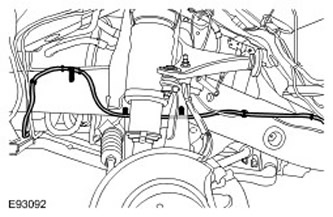
20. Left Front: Disconnect the frame wiring harness from the frame. Release the 6 clamps.
21. Remove the air suspension bladder. For more information, refer to Air Suspension Bladder (60.50.03)
22. Left side: Disconnect the air suspension line from the frame wiring harness. Release the 4 clamps.
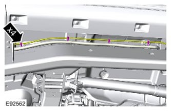
23. Left side: Disconnect the frame wiring harness from the frame. Release the 6 clamps.
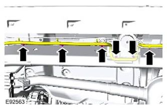
24. Remove the air suspension muffler. For more information, refer to Air Suspension Muffler (64.50.01)
All except diesel vehicles
25. Remove the EVAP canister. For more information, refer to Evaporative Emissions Canister (17.15.13)
All cars
26. Disconnect the 2 electrical connectors from the air suspension solenoid valve.
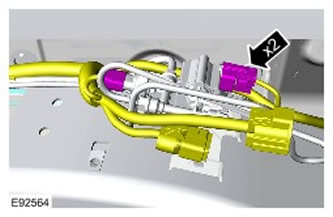
27. Release the air suspension compressor valve block. Release the 3 sealing bushings.
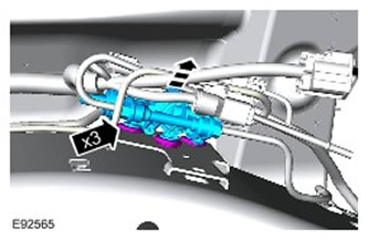
28. Left side: Disconnect the air suspension line from the frame wiring harness.
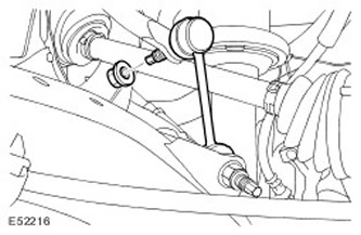
29.
CAUTION: Use a hex key to prevent the ball joint from turning.
- Remove both stabilizer bar struts.
- Unscrew the two nuts.
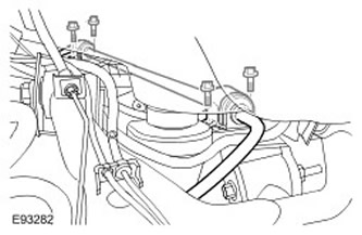
30. Release the stabilizer. Unscrew 4 bolts.
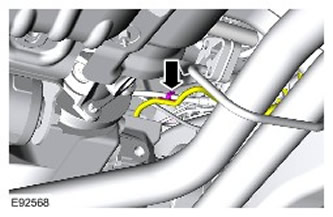
31. Disconnect the frame wiring harness from the parking brake cable.
32. Vehicles with electric differential lock motor: Disconnect the 2 electrical connectors. Release the 2 wiring harness clamps.
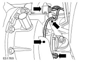
33. Disconnect the parking brake emergency release cable. Release the 2 clamps.
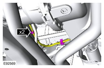
34. Left side: Release the frame wiring harness. Remove the bolt.
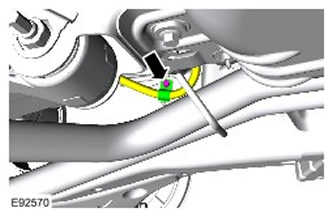
35. Disconnect the electrical connector from the rear left height sensor. Release the 2 clamps.
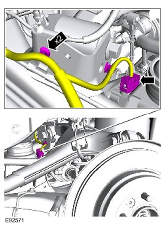
36. Left rear: Disconnect the electrical connector of the rear air suspension valve block. Release the clamp.
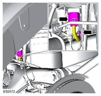
37. Remove the valve block from its support bracket. Release the 3 sealing bushings.
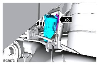
38. Position the frame wiring harness over the frame.
39. Left rear: Disconnect the 2 electrical connectors from the frame wiring harness. Release the two electrical connectors.
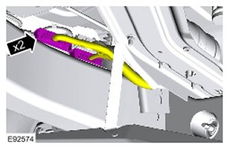
40. Disconnect the left rear ABS sensor. Release the clamp.
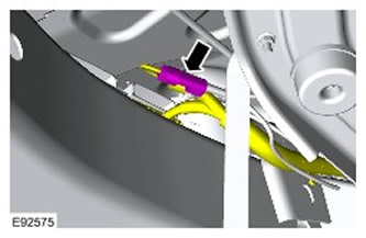
41. Disconnect the parking brake actuator support bracket.
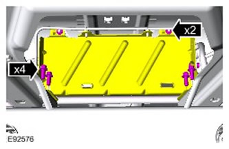
42. Spare wheel opening: Release the frame wiring harness. Release the 5 clamps.
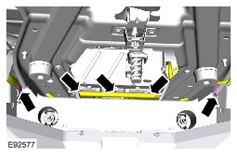
43. Right rear: Disconnect the electrical connector of the ABS sensor. Release the 2 clamps.
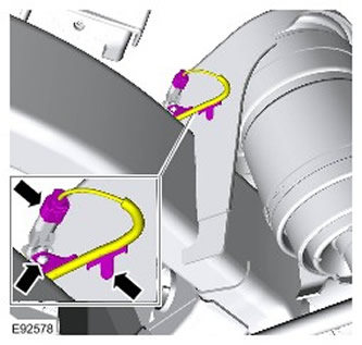
44. Right rear: Disconnect the electrical connector of the brake pad wear indicator lamp. Release the 2 clamps.
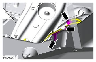
45. Disconnect the electrical connector of the electronic parking brake actuator. Release the clamp.
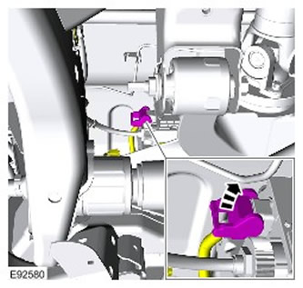
46. Disconnect the right parking brake cable.
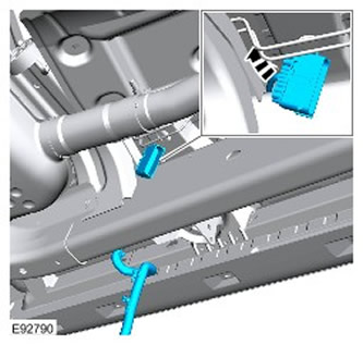
- Remove the bolt.
- Release the clamp.
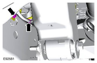
47. Loosen the fuel line support bracket fastening.
- Remove the inner section of the fuel line support bracket.
- Release the clamp.
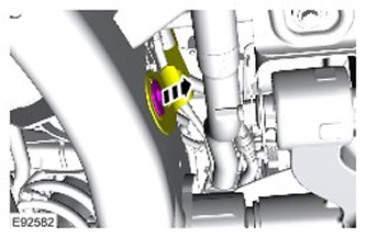
48. Disconnect the frame wiring harness from the parking brake cable.
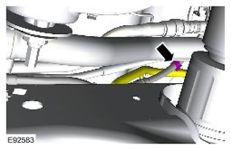
49. Right side: Disconnect the frame wiring harness from the frame.
50. Remove the gearbox protective screen. Unscrew 6 bolts.
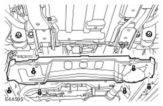
51. Remove the fuel tank heat shield. Remove 3 bolts and 2 nuts.
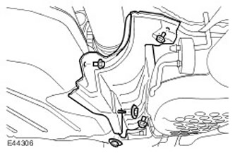
52. Disconnect the parking brake emergency release cable. Release the 4 clamps.
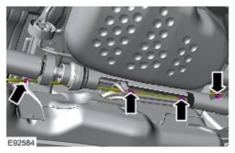
53.
CAUTION: Secure the assembly to a transmission jack.
NOTE: Please note that there are two washers on the rear bolt.
Using a transmission jack, lower the fuel tank. Remove the 6 bolts.
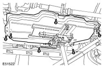
54. Disconnect the fuel pump module electrical connector.
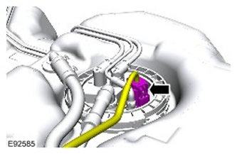
55. Disconnect the frame wiring harness from the fuel tank.
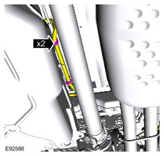
56. Rear of Fuel Tank: Disconnect the frame wiring harness from the top of the frame crossmember. Release the clamp.
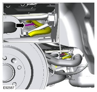
57. Disconnect the 2 electrical connectors from the frame wiring harness. Release the 2 clamps.
Diesel Engine Cars
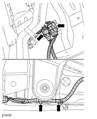
58. Disconnect the fuel fired auxiliary heater pump electrical connector. Release the three clamps.
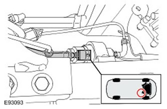
All cars
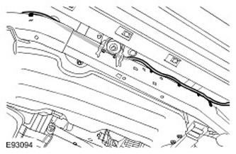
59. Right side: Disconnect the frame wiring harness from the frame. Release the 9 clamps.
60. Secure the fuel tank.
61. To gain access, disconnect the exhaust system heat shield.
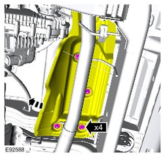
62. Release the brake pipes.
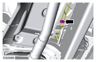
63. Using outside help, remove the frame wiring harness.
- Position both ends of the frame wiring harness on the left center support post.
- Route the front end of the frame wiring harness between the body and the center cross member.
Installation
All cars
1. Compare the old frame wiring harness with the new wiring harness to make sure they are the same.
2.
NOTE: Make sure the wiring harness is positioned correctly.
With outside help, install the frame wiring harness. Reinstall all electrical connectors and clamps of the frame wiring harness.
3. Secure the brake lines.
4. Secure the exhaust system heat shield.
5.
CAUTION: Secure the assembly to a transmission jack.
NOTE: Please note that there are two washers on the rear bolt.
Using a transmission jack, lower the fuel tank. Remove the 4 bolts.
6. Right side: Secure the frame wiring harness to the frame. Secure with 9 clips.
Diesel Engine Cars
7. Connect the fuel fired auxiliary heater pump electrical connector. Secure the three clamps.
All cars
8. Connect the 2 electrical connectors to the frame wiring harness. Release the 2 clamps.
9. Connect the fuel pump module electrical connector.
10. Right side: Connect the frame wiring harness to the fuel tank.
11. Rear of Fuel Tank: Connect the frame wiring harness to the top of the frame cross member.
12.
NOTE: Please note that there are two washers on the rear bolt.
Install the fuel tank. Tighten the bolts. (tightening torque 45 Nm).
13. Secure the parking brake emergency release cable. Secure with 4 clamps.
14. Install the fuel tank heat shield.
- Tighten the bolts (tightening torque 6 Nm).
- Tighten the nuts (tightening torque 3 Nm).
16. Right side: Secure the frame wiring harness to the frame.
17. Connect the frame wiring harness to the right parking brake cable.
18. Secure the right parking brake cable bracket.
- Install the inner section of the parking brake cable bracket.
- Secure the clamp.
- Secure the clamp.
- Tighten the new bolts. (tightening torque 22 Nm).
21. Right rear: Connect the electrical connector of the brake pad wear indicator lamp. Secure the 2 clamps.
22. Right rear: Connect the electrical connector of the ABS sensor. Secure the 2 clamps.
23. Spare tire opening: Secure the frame wiring harness. Secure the 5 clips.
24. Secure the parking brake actuator support bracket. Tighten the bolts. (tightening torque 22 Nm).
25. Connect the left rear ABS sensor. Secure the clamp.
26. Left rear: Connect the 2 electrical connectors to the frame wiring harness. Secure the electrical connectors.
27. Relocate the rear valve block electrical connector.
28. Relocate the electrical connector of the right suspension height sensor.
29. Left rear: Connect the electrical connector of the air suspension valve block. Secure the clamp.
30. Connect the electrical connector to the rear left height sensor. Secure the clamp.
31. Secure the valve block to its support.
32. Left side: Secure the frame wiring harness. Tighten the bolt. (tightening torque 22 Nm).
33. Secure the parking brake emergency release cable. Secure with clamps.
34. Connect the frame wiring harness to the left parking brake cable.
35. Attach both stabilizer bar struts. Tighten the nuts. (tightening torque 15 Nm).
36. Secure the stabilizer. Tighten the bolts. (tightening torque 62 Nm).
37. Secure the air suspension compressor valve block.
38. Connect the electrical connectors to the air suspension solenoid valve.
All except diesel vehicles
39. Install the fuel vapor canister. For more information, refer to Fuel Evaporative Control System Charcoal Canister (17.15.13)
All cars
40. Install the air suspension muffler. For more information, refer to Air Suspension Muffler (64.50.01)
41. Left side: Attach the air suspension line to the frame wiring harness.
42. Left side: Secure the frame wiring harness to the frame. Secure the 6 clips.
43. Install the air suspension bladder. For more information, refer to Air Suspension Bladder (60.50.03)
44. Connect the 3 electrical connectors to the frame wiring harness.
45. Connect the ground wire to the ground contact of the wheel arch.
- Tighten the nut (tightening torque 25 Nm).
- Secure 2 clamps.
47. Left front side: Connect the height sensor electrical connector.
48. Install the left front fender splash guard.
49. Move the frame wiring harness to the right front wheel arch.
50. Connect the frame wiring harness to the front frame cross member.
- Release the 2 air suspension lines.
- Release the three clamps.
52. Right side: Secure the frame wiring harness to the frame.
53. Right Front: Install the suspension height sensor. For more information, refer to Suspension Height Sensor (60.36.01)
54. Install the upper arm and brake line heat shields.
- Screw in 3 bolts.
- Screw on 3 nuts.
56. Install the front bumper cover. For more information, refer to Front Bumper Cover (76.22.72)
57. Install the wheels with tires. Tighten the wheel nuts. (tightening torque 140 Nm).
58. Install the spare wheel and tire.
59. Connect the ground cable to the battery. For more information, refer to Specification.
Comments on this article