Removing
1. Disconnect the wire "masses" from the battery. For more information refer to Specification.
2. Remove the motor shield. For more information refer to Motor Protection (76.10.50)
3. Remove the intake manifold. For more information refer to Intake Manifold (30.15.02)
4. Remove the battery. For more information refer to Battery (86.15.01)
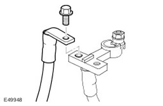
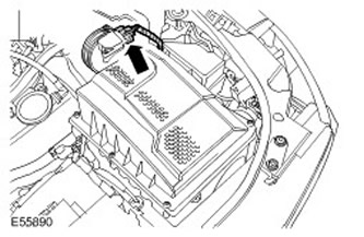
5. Remove the main power cable from the fuse box in the engine compartment. Turn out a bolt.
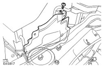
6. Remove the top heat-shielding screen of a motor compartment.
- Remove the screw.
- Release 2 fixing clips.
7. Remove the side wall of the battery compartment.
- Release the positive battery cable and grommet.
- Release 4 clips.
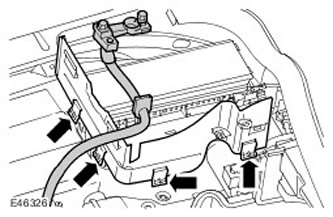
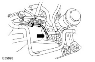
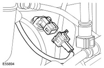
8. Remove the engine wiring harness from the battery compartment. Disconnect the two electrical connectors.

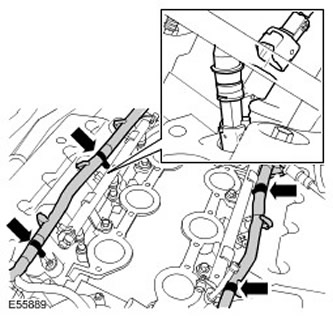
9. Release the 2 clips on the protective cover of the wiring harness.

10. Disconnect the fuel injector electrical connectors. Release 4 clips.
11. Disconnect the electrical connector of the mass air flow sensor (MAF). Release the clamp.
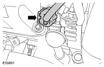
12. Disconnect the engine coolant temperature sensor electrical connector (ECT).
13. Disconnect the electrical connector of the generator.
14. Disconnect the knock sensor electrical connectors (KS).
15. Disconnect the cooling fan electrical connector. Release 2 clips.
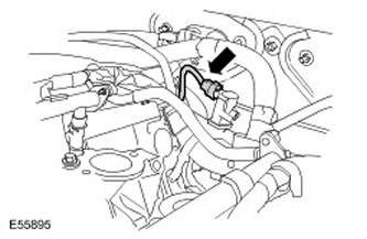
16. Disconnect the camshaft position sensor electrical connector (CMP). Release the clamp.
17. Disconnect purge valve electrical connector (PCV).
18. Disconnect the left breather electrical connector.
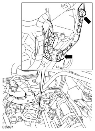
19. Remove the wiring harness bridge. Turn out 2 bolts.
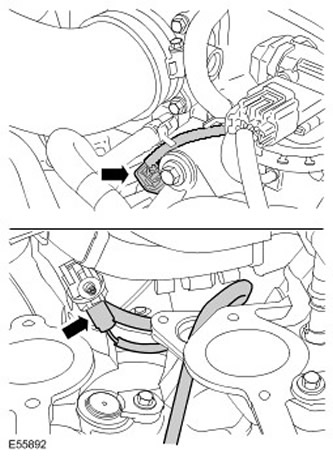
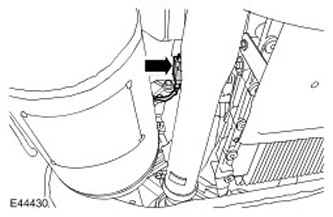
20. Disconnect the left HO2S and release the clip.
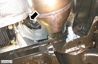
21. Disconnect the right HO2S and release the clip.
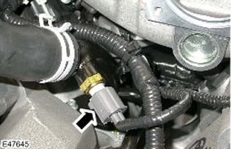
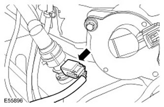
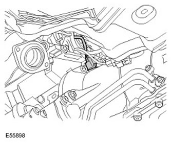
22. Disconnect the electrical connector of the crankshaft position sensor (TFR).
23.
NOTE: Remember the position of the part.
Remove the engine wiring harness.
Installation
1.
NOTE: Align the part to its original position.
Install the engine wiring harness.
2. Connect the electrical connector of the crankshaft position sensor (CKP).
3. Connect the heated oxygen sensor electrical connectors.
4. Install the wiring harness bridge. Tighten the bolts (tightening torque 45 Nm).
5. Connect the breather electrical connector.
6. Connect the PCV valve electrical connector.
7. Connect the CMP sensor electrical connector. Fasten the clamp.
8. Connect the cooling fan electrical connector. Fasten the clips carefully.
9. Connect the electrical connectors of the KS sensor.
10. Install the generator.
11. Connect the ECT sensor electrical connector.
12. Connect an electric socket of the gauge MAF. Fasten the clamp.
13. Connect electric sockets of fuel atomizers. Secure the clips carefully.
14. Connect the engine wiring harness.
- Install the clamps on the protective cover of the wiring harness.
- Connect and secure the electrical connectors.
- Fasten the clamps.
- Install the positive battery cable and grommet.
- Fasten the clamps.
- Tighten the screw.
18. Install the battery. For more information refer to Battery (86.15.01)
19. Install the intake manifold. For more information refer to Intake Manifold (30.15.02)
20. Install the engine shield. For more information refer to Motor Protection (76.10.50)
21. Connect the wire "masses" to the battery. For more information refer to Specification.
Comments on this article