Contents: Removal ⇩ Installation ⇩
Removal
All cars
1. Disconnect the ground cable from the battery. For more information, refer to Specification.
2. Switch the SRS system to safe mode. For more information, refer to the Standard Techniques used at the service station.
3. Remove the engine cover. For more information, refer to Engine Cover - 4.4L (12.30.50)
4. Remove the radiator grille. For more information, refer to Radiator Grille (76.55.03)
5. Remove the air cleaner assembly. For more information, refer to Air Cleaner (10/19/01)
6. Remove the all-wheel drive control module. For more information, refer to Four-Wheel Drive (4WD) Control Module (41.30.01)
7. Remove the battery tray. For more information, refer to Battery Shelf (76.10.30)
8. Remove the extra battery tray. For more information, refer to Extra Battery Shelf (76.10.31)
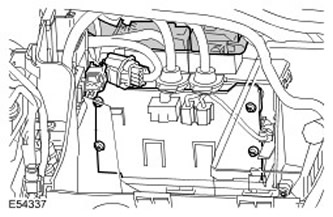
9. Remove the ECM cover.
- Disconnect 2 electrical connectors to gain access.
- Disconnect the 2 ECM electrical connectors.
- Remove 4 Torx head screws.
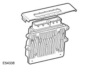
10. Remove the ECM. Remove the ECM upper cover.
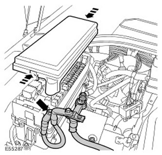
11. Remove the BJB cover. Release the clamp.
12. Disconnect the positive battery cable from the BJB. Remove the nut.
13. Remove both door jamb trim panels. For more information, refer to Front Door Jamb Trim Panel (76.13.27)
14. Remove the CJB. For more information, refer to Central Junction Box (CJB) (86.70.56)
15. Release the CJB bracket.
- Release the 3 upper wiring harness clips.
- Remove 2 bolts.
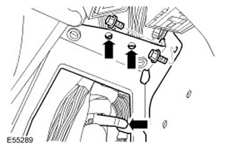
16. Remove the CJB bracket.
- Disconnect the two electrical connectors.
- Release the 3 lower wiring harness clips.
- Unscrew 2 nuts.
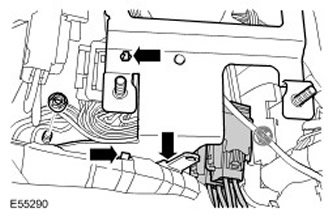
17. Disconnect the 2 ground cables from the bottom of the A-pillar. Remove the nut.
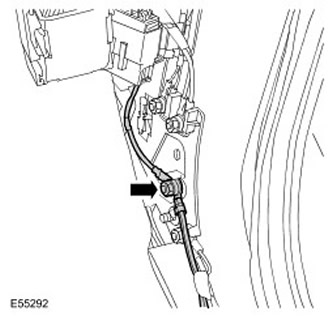
18. Disconnect the heater motor electrical connector.
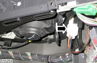
19. Remove the BJB from the bracket. Remove the bolt.
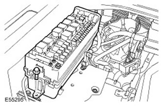
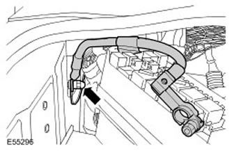
20. Disconnect the ground wire from the battery.
- Unscrew the nut.
- Release the additional ground cable.
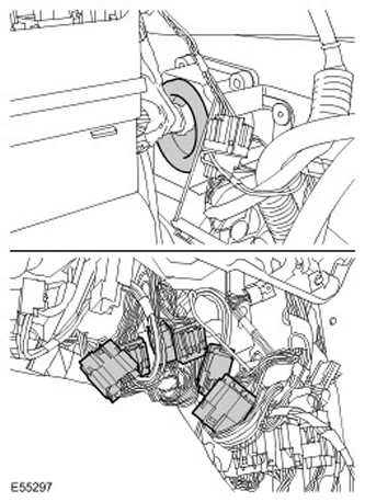
21. Remove the BJB wiring harness from the bulkhead.
- Disconnect 6 electrical connectors.
- Release the sealing sleeve.
22. Raise and support the vehicle.
23. Remove the mudguards from both front wings. For more information, refer to Mudguard (76.10.48)
24. Remove both headlamps. For more information, refer to Headlamp Assembly (86.40.49)
25. Passenger side: Disconnect the engine wiring harness electrical connector.
26. Passenger side: Disconnect the transfer case electrical connector.
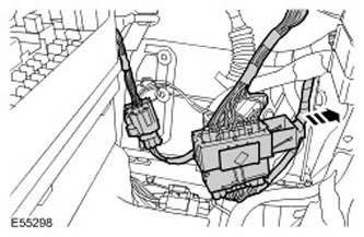
27. Left side: Disconnect the windshield washer hose.
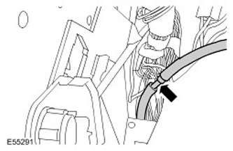
28. Left side: Disconnect the electrical connector of the adaptive headlight controller.
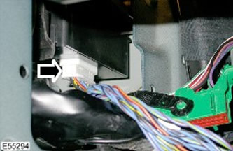
Cars with additional climate control
29. Left side: Remove the air conditioning pipes from the body panel. Unscrew the nut.
All cars
30. Left side: Disconnect the 3 body panel electrical connectors.
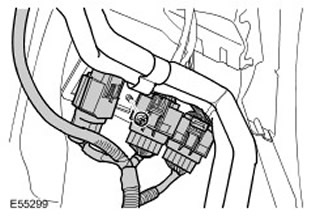
31. Left side: Remove the ground cables from the three body panels. Remove the nut.
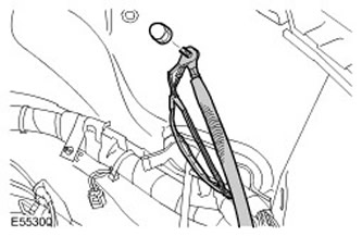
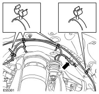
32. Left side: Release the 2 air suspension lines from the wiring harness. Release the 7 clamps.
33. Left side: Disconnect the ABS electrical connectors.
34. Left side: Release the 3 engine compartment ground cables.
- Unscrew 3 nuts.
- Release the 2 clamps.
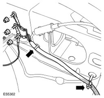
35. Left side: Remove the washer reservoir wiring harness.
- Disconnect 2 electrical connectors.
- Disconnect the 2 washer nozzle hoses.
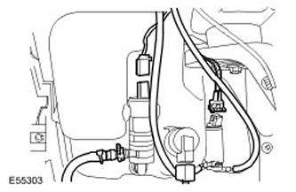
36. Left side: Disconnect the electrical connector of the coolant level sensor in the expansion tank.
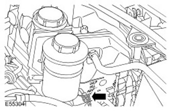
37. Left side: Disconnect the electrical connector of the brake pad wear sensor.
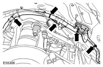
38. Left side: Remove the wiring harness.
- Release the sealing sleeve.
- Release the 4 clamps.
39. Remove the windshield wiper motor. For more information, refer to Windshield Wiper Motor (84.15.12)
40. Remove the hood trim. Remove 11 clips.
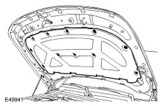
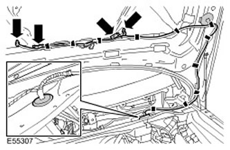
41. Remove the hood wiring harness.
- Disconnect the 2 washer nozzle hoses.
- Disconnect the two electrical connectors.
- Release 10 clamps.
- Remove the wiring harness cover.
- Release the sealing sleeve.
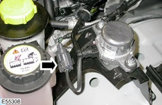
42. Disconnect the brake booster vacuum pump electrical connector.
43.
NOTE: The illustration shows a 4.0L engine model. The procedure is similar for a 4.4L engine model.
Disconnect the air conditioning pressure sensor electrical connector.
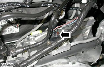
44.
NOTE: The illustration shows a 4.0L engine model. The procedure is similar for a 4.4L engine model.
Disconnect the electrical connector from the wiring harness that runs from the battery to the engine compartment.
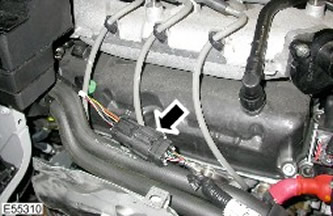
45.
NOTE: The illustration shows a 4.0L engine model. The procedure is similar for a 4.4L engine model.
Remove the wiring harness from the manifold.
- Release the 2 clamps.
- Unscrew 3 nuts.
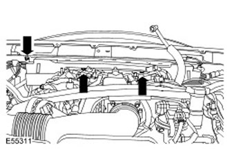
46. Disconnect the brake fluid reservoir electrical connector.
47. Disconnect the ABS unit electrical connector.
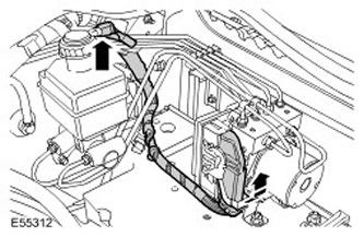
48. Remove the air suspension control module. For more information, refer to Air Suspension Control Module (60.50.04)
49. Driver side: Disconnect the 2 electrical connectors from the lower A-pillar.
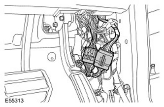
50. Driver's side: Remove the wiring harness from the bulkhead. Release the sealing grommet.
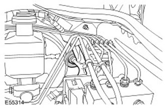
Cars with additional heating
51. Right side: Remove the heater pipes from the body panel. Unscrew the nut.
All cars
52. Right side: Disconnect the 3 body panel electrical connectors.
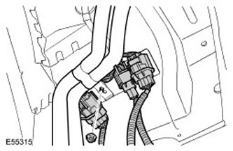
53. Right side: Remove the ground cables from the three body panels. Remove the nut.
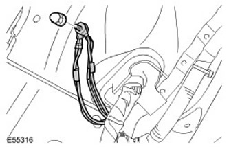
54. Right side: Disconnect the ABS electrical connectors.
55. Right side: Remove the air suspension line from the wiring harness clamp.
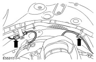
56. Right side: Release the 2 engine compartment ground cables. Remove the 2 nuts.
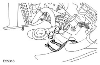
57. Disconnect the ambient air temperature sensor electrical connector.
58. Disconnect both electrical connectors of the front impact severity sensor. Release the 3 clips.
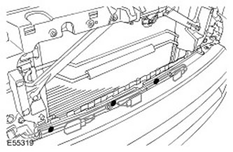
59. Right side: Remove the wiring harness. Release the 9 clips.
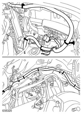
60. Disconnect the hood switch electrical connector.
61. Disconnect both horn electrical connectors.
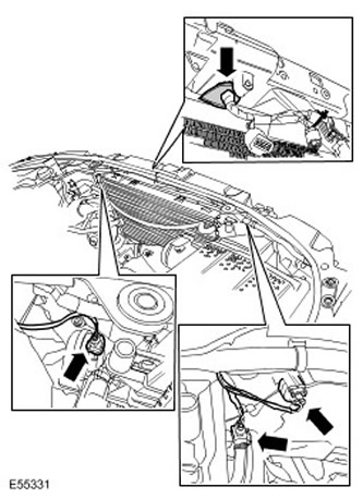
62. Disconnect the cruise control unit electrical connector, if equipped.
63. Disconnect the pollution sensor electrical connector, if equipped.
- Release the clamp.
- Release the sealing sleeve.
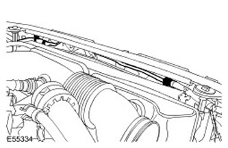
65. Disconnect the front bumper wiring harness electrical connector.
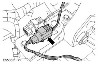
66. With assistance, remove the BJB and wiring harness.
Installation
All cars
1. With assistance, install the BJB and wiring harness.
2. Connect the front bumper wiring harness electrical connector.
3. Attach the hood release cable. Secure with clamps.
4. Connect the pollution sensor electrical connector, if equipped.
- Install the sealing bushing.
- Secure the clamp.
6. Connect the horn electrical connectors.
7. Connect the hood switch electrical connector.
8. Right side: Secure the wire harness. Secure the clamps.
9. Connect both electrical connectors of the front impact severity sensor. Secure the clamps.
10. Right side: Connect the air suspension line.
11. Connect the ambient air temperature sensor electrical connector.
12. Right side: Connect the engine compartment ground cables. Tighten the nuts. (tightening torque 25 Nm).
13. Right side: Connect the ABS electrical connector.
14. Right side: Connect the ground cables of the three body panels. Tighten the nut. (tightening torque 25 Nm).
15. Right side: Connect the electrical connectors of the body panel.
Cars with additional heating
16. Right side: Secure the heater pipes to the body panel. Tighten the nut. (tightening torque 10 Nm).
All cars
17. Driver's side: Attach the wiring harness to the bulkhead. Install the grommet.
18. Driver's side: Connect the electrical connectors at the bottom of the A-pillar.
19. Install the air suspension control module. For more information, refer to Air Suspension Control Module (60.50.04)
20. Connect the ABS unit electrical connector.
21. Connect the brake fluid reservoir electrical connector.
22. Connect the wiring harness to the manifold.
- Secure the clamps.
- Tighten the nuts (tightening torque 4 Nm).
24. Connect the electrical connector of the air conditioner pressure sensor.
25. Connect the brake booster vacuum pump electrical connector.
26. Secure the hood wiring harness.
- Install the sealing bushing.
- Install the lid.
- Secure with clamps.
- Connect the electrical connectors.
- Connect the washer nozzle hoses.
28. Install the windshield wiper motor. For more information, refer to Windshield Wiper Motor (84.15.12)
29. Left side: Secure the wiring harness.
- Install the sealing bushing.
- Secure the clamps.
31. Left side: Connect the electrical connector of the coolant level sensor in the expansion tank.
32. Left side: Connect the washer reservoir wiring harness.
- Connect the washer nozzle hoses.
- Connect the electrical connectors.
- Secure the clamps.
- Tighten the nuts (tightening torque 25 Nm).
35. Left side: Connect the air suspension lines. Secure the clamps.
36. Left side: Connect the ground cables of the three body panels. Tighten the nut. (tightening torque 25 Nm).
37. Left side: Connect the electrical connectors of the body panel.
Cars with additional climate control
38. Left side: Secure the air conditioning pipes to the body panel. Tighten the nut. (tightening torque 10 Nm).
All cars
39. Left side: Connect the electrical connector of the adaptive headlight controller.
40. Left side: Connect the washer nozzle hose.
41. Passenger side: Connect the transfer case electrical connector.
42. Passenger side: Connect the engine wiring harness electrical connector.
43. Install the headlamps. For more information, refer to Headlamp Assembly (86.40.49)
44. Install the front fender splash guards. For more information, refer to Fender Splash Guard (76.10.48)
45. Connect the BJB wiring harness to the bulkhead.
- Connect the electrical connectors.
- Install the sealing bushing.
- Connect the additional ground cable.
- Tighten the nut (tightening torque 25 Nm).
48. Connect the heater motor electrical connector.
49. Attach the ground cables to the bottom of the A-pillar. Tighten the nut. (tightening torque 10 Nm).
50. Install the CJB bracket.
- Tighten the nuts (tightening torque 10 Nm).
- Secure the clamps.
- Connect the electrical connectors.
- Tighten the bolts (tightening torque 25 Nm).
52. Connect the positive battery cable to the BJB. Tighten the nut. (tightening torque 25 Nm).
53. Install the BJB cover. Secure the clamp.
54. Install the ECM. Install the ECM upper cover.
55. Install the ECM cover.
- Tighten the Torx head screws.
- Connect the electrical connectors.
57. Install the battery tray. For more information, refer to Battery Installation Shelf (76.10.30)
58. Install the all-wheel drive control module. For more information, refer to Four-Wheel Drive (4WD) Control Module (41.30.01)
59. Install the air cleaner assembly. For more information, refer to Air Cleaner (10/19/01)
60. Install the radiator grille. For more information, refer to Radiator Grille (76.55.03)
61. Install the engine cover. For more information, refer to Engine Cover - 4.4L (12.30.50)
62. Connect the ground cable to the battery. For more information, refer to Specification.
63. Check that the headlight beam is adjusted correctly. For more information, refer to Headlight Adjustment (86.40.17)
Comments on this article