Contents: Removal ⇩ Installation ⇩
Removal
1. Remove the bumper mount. Refer to procedure: Front Bumper (501-19 Bumpers, Removal and Installation).
2. Remove the air cleaner housing. Refer to the procedure: Air Cleaner (303-12A Intake Air Distribution and Filtration - 3.2L NA - I6, Removal and Installation).
3. Remove the secondary bulkhead center panel. Refer to procedure: Secondary Bulkhead Center Panel - 2.2L Duratorq - Td4 (501-02 Front Body Panels, Removal and Installation).
4. Remove the brake booster. Refer to the procedure: Brake Booster (206-07 Brake Booster, Removal and Installation).
5. Remove the ABS module. Refer to procedure: Anti-lock Brake System (ABS) Module (206-09A Anti-lock Brake System, Removal and Installation).
6. Remove the fuel fired auxiliary heater. Refer to procedure: Fuel Fired Auxiliary Heater (412-02 Auxiliary Climate Control, Removal and Installation).
7. Remove both headlights. Refer to procedure: Headlight Assembly (417-01 Exterior Lighting, Removal and Installation).
8. Remove the upper engine mount. Refer to procedure: Upper Engine Mount Insulator (303-01A Engine - 3.2L NA - I6, Removal and Installation).
9. Remove the glove compartment cover. Refer to procedure: Glove Compartment (501-12 Instrument Panel and Console, Removal and Installation).
10. Remove the left wing splash guard.
NOTE: Right hand drive version shown, left hand drive version similar.
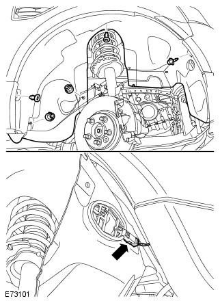
11.
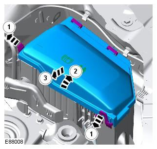
12.
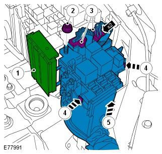
13.
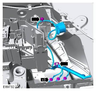
14.
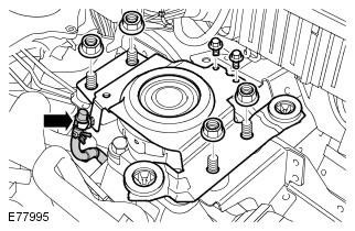
15.
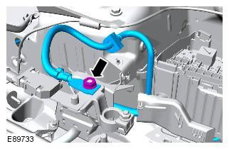
16.
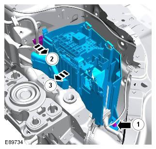
17.
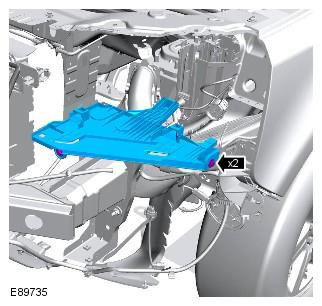
18.
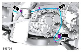
19.
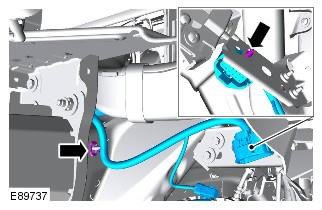
20. Release the wiring harness and pull it into the engine compartment area.
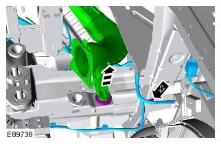
21.
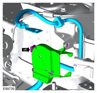
22.
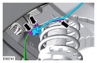
23.
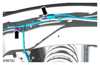
24.
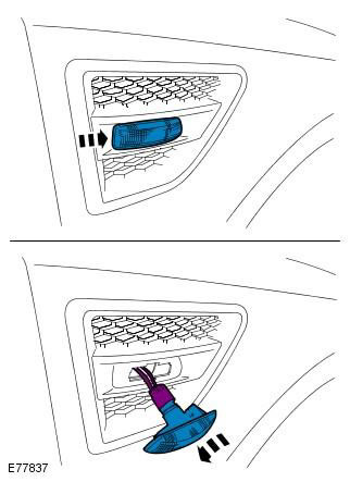
25.
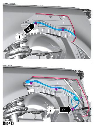
26.
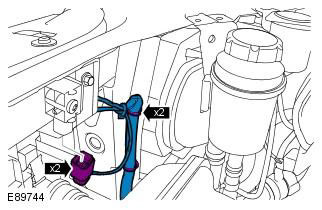
27.
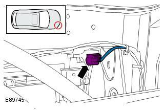
28.
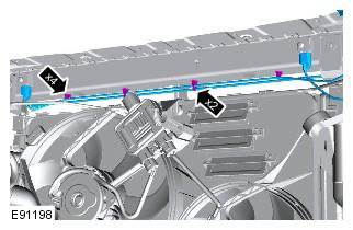
29.
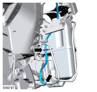
30.
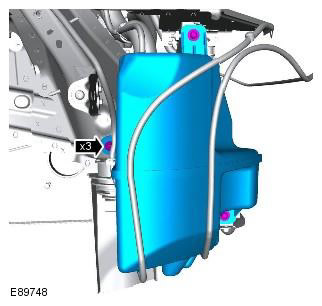
31.
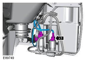
32.
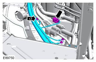
33.
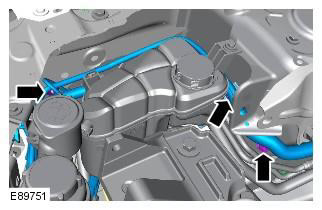
34.
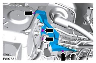
35. Disconnect the heated windshield electrical connector from the extension panel on the vent chamber side and remove the panel.
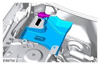
36.
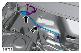
37.
NOTE: Left hand drive version shown, same for right hand drive version.
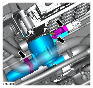
38.
NOTE: Left hand drive version shown, same for right hand drive version.
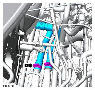
39.
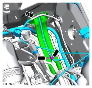
40.
NOTE: Left hand drive version shown, same for right hand drive version.
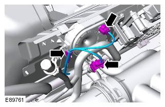
41. Release the engine compartment wiring harness from the clip that secures it to the vehicle bulkhead.
NOTE: Left hand drive version shown, same for right hand drive version.
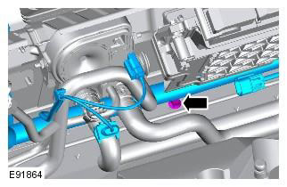
42. NOTE: Right hand drive version shown, left hand drive version similar.
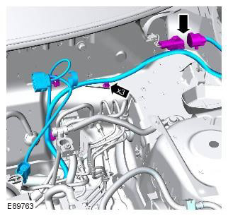
43.
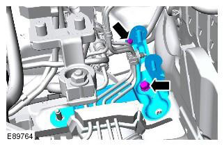
44.
NOTE: Left hand drive version shown, same for right hand drive version.
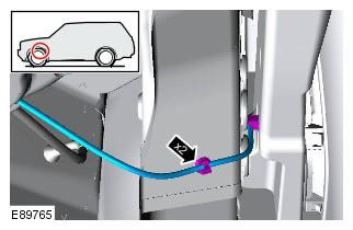
45.
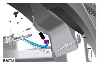
46. NOTE: Left hand drive version shown, same for right hand drive version.
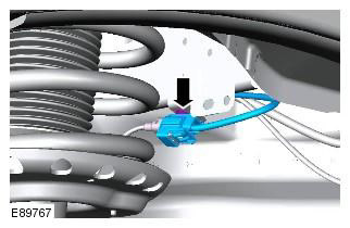
47. Disconnect the left repeater from the body and unplug the electrical connector.
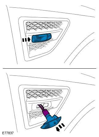
48.
NOTE: Left hand drive version shown, same for right hand drive version.
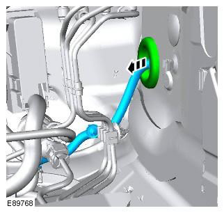
49. Disconnect the wiring harness tray from the vehicle bulkhead and route the right side of the harness around the brake lines to the left side of the engine compartment.
50.
NOTE: Right hand drive version shown, left hand drive version similar.
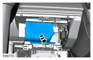
51.
NOTE: Right hand drive version shown, left hand drive version similar.
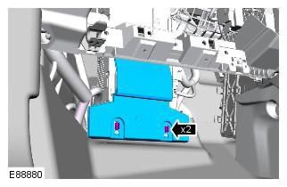
52.
NOTE: Right hand drive version shown, left hand drive version similar.
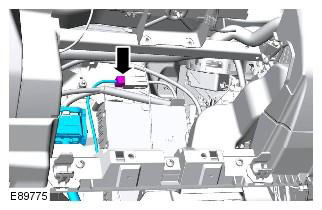
53.
NOTE: Right hand drive version shown, left hand drive version similar.
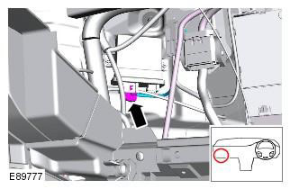
54.
NOTE: Right hand drive version shown, left hand drive version similar.
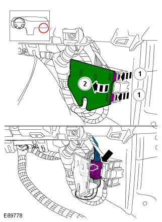
55.
NOTE: Right hand drive version shown, left hand drive version similar.
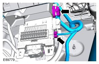
56.
NOTE: Right hand drive version shown, left hand drive version similar.
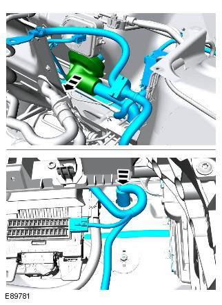
Installation
1. Install the wiring harness onto the vehicle's ventilation chamber, pull the connectors into the vehicle's interior, and install the rubber grommet. You will need an assistant inside the vehicle to pull the connectors into the vehicle's interior.
2. Secure the wiring harness tray clamps and secure the rubber grommet to the vehicle body.
3. Install and secure the fuse box to the vehicle body. Tightening torque: 10 Nm
4. Install the engine support plate. Tightening torque: M8 24 Nm. M12 80 Nm
5. Connect the engine wiring harness to the fuse box.
6. Connect the battery cable to the fuse box and secure it and install the small battery cable cover. Tightening torque: 10 Nm
7. Connect the two electrical connectors to the BJB.
8. Fix the 3 grounding points and secure the wiring harness clamps to the vehicle body. Tightening torque: 10 Nm
9. Secure the battery cable to the battery terminal clamp. Tightening torque: 25 Nm
10. Install the fuse box cover.
11. Install the wiring harness cover onto the suspension strut dome.
12. Route the wiring harness under the air cleaner duct and secure the duct to the rubber grommet.
13. Secure the headlight and bumper wiring harness clamps.
14. Connect the height sensor electrical connector and secure the wiring harness with clamps.
15. Install the headlight mounting panel. Tightening torque: 10 Nm
16. Connect the side repeater electrical connector.
17. Connect the heated washer nozzle electrical connection and attach the wiring harness to the vehicle body.
18. Connect the ABS sensor and attach the wiring harness to the vehicle body.
19. Attach the washer line to the wiring harness and attach the wiring harness to the body.
20. Connect the electrical connectors of the impact sensor.
21. Connect the hood lock electrical connector.
22. Attach the wiring harness to the body and then attach the hood release cable to the wiring harness.
23. Attach the washer pipe to the washer reservoir.
24. Install the washer reservoir and connect the electrical connections. Tightening torque: 10 Nm
25. Attach the 3 ground wires to the car body. Tightening torque: 10 Nm
26. Attach the wiring harness to the vehicle body.
27. Connect the hood lock electrical connector.
28. Install the right secondary bulkhead support bracket. Tightening torque: 10 Nm
29. Install the inner plenum plate and attach the electrical connector to the plate.
30. Connect the right windshield heating electrical connector.
31. Install the additional coolant pump and connect the supply hose. Tightening torque: 10 Nm
32. Install the fuel fired auxiliary heater coolant supply and return lines.
33. Connect the fuel-fired auxiliary heater coolant supply and return hoses to the pipes.
34. Connect the electrical connectors of the air conditioner pressure sensor and BBUS. Also attach the wiring harness to the car body.
35. Secure the engine compartment wiring harness to the vehicle bulkhead.
36. Attach the wiring harness tray to the left side of the vehicle bulkhead.
37. Connect the left heated windshield electrical connector and attach the wiring harness to the vehicle body.
38. Route the wiring harness into the left wheel arch and secure the rubber grommet.
39. Install the ABS modulator bracket. Tightening torque: 25 Nm
40. Install the left side repeater lamp and attach the clamps to the vehicle body.
41. Connect the rear window washer line.
42. Connect the ABS sensor electrical connector and attach the wiring harness to the vehicle body.
43. Connect the two electrical connectors to the CJB.
44. Connect the engine compartment main wiring harness to the instrument panel wiring harness and close the cover.
45. Connect the engine compartment main wiring harness to the headlight leveling system electronic control unit.
46. Connect the three electrical connections of the floor wiring harness.
47. Install the fuse box cover and sound insulation.
48. Install the left wing splash guard. Tightening torque: 6 Nm
49. Install the glove compartment cover. Refer to procedure: Glove Compartment (501-12 Instrument Panel and Console, Removal and Installation).
50. Install the upper engine mount. Refer to procedure: Upper Engine Mount Insulator (303-01A Engine - 3.2L NA - I6, Removal and Installation).
51. Install both headlamps. Refer to procedure: Headlamp Assembly (417-01 Exterior Lighting, Removal and Installation).
52. Install the fuel fired auxiliary heater. Refer to procedure: Fuel Fired Auxiliary Heater (412-02 Auxiliary Climate Control, Removal and Installation).
53. Install the ABS module. Refer to procedure: Anti-lock Brake System (ABS) Module (206-09A Anti-lock Brake System, Removal and Installation).
54. Install the brake booster. Refer to procedure: Brake Booster (206-07 Brake Booster, Removal and Installation).
55. Install the secondary bulkhead center panel. Refer to procedure: Secondary Bulkhead Center Panel - 2.2L Duratorq - Td4 (501-02 Front Body Panels, Removal and Installation).
56. Install the air cleaner housing. Refer to procedure: Air Cleaner (303-12A Intake Air Distribution and Filtration - 3.2L NA - I6, Removal and Installation).
57. Install the bumper mount. Refer to procedure: Front Bumper (501-19 Bumpers, Removal and Installation).
Comments on this article