


Contents: Dismantling ⇩ Assembly ⇩
Before disconnecting the battery, make sure that all requirements and conditions contained in the section on disconnecting the battery are met.
GENERAL INFORMATION, Precautions when working with electrical equipment.
Dismantling
1. Place the vehicle on a lift.
2. Disconnect the negative terminal from the battery.
3. Remove the cover that covers the engine in the engine compartment.
TD6 ENGINE, REPAIR WORK, Upper engine casing.
4. Remove the viscous coupling with the fan.
COOLING SYSTEM: Td6, REPAIR WORK, Viscous fan clutch.
5. Place the vehicle on a lift.
6. Drain the working fluid from the transfer case.
TRANSFER CASE, ADJUSTMENTS, Draining and filling the working fluid.
7. Remove the rear propeller shaft.
DRIVE SHAFTS, REPAIR WORK, Cardan shaft - rear.
8. Remove the front propeller shaft.
DRIVE SHAFTS, REPAIR WORK, Cardan shaft - front.
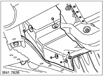
9. Unscrew 5 nuts and remove the right heat shield.
10. Install and position the jack under the transfer case housing.
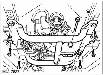
11. Remove the bolt and nut connecting the transmission support assembly to the cross frame.
12. Remove the 6 cross frame mounting screws and remove the cross frame.
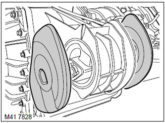
13. Remove the silent block from the support.
14. Lower the gearbox using a jack.
CAUTION: Do not allow the transmission to hang by the gear selector cable.
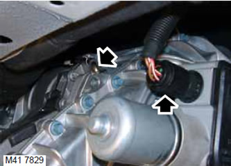
15. Remove the connector from the transfer case gear shift drive unit connector.
16. Remove the transfer case crankcase ventilation hose.
CAUTION: Always plug the fittings and holes to protect the system from dirt.
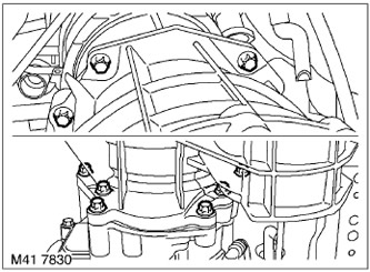
17. Support the transfer case with a jack.
18. Remove the 9 Torx screws and remove the transfer case.
NOTE: Do not perform further disassembly if the unit is removed only for ease of access.
19. Remove the 3 Torx screws securing the vibration damper and remove the vibration damper.
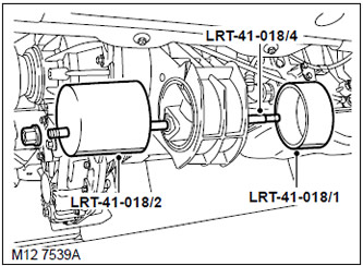
20. Apply molybdenum grease to the center screw of the LRT-41-018/4 tool and assemble the tool to remove the support from the transfer case as shown in the figure.
CAUTION: Make sure the alignment indicator of the fixture is in the lowest position. The alignment indicator is the flat groove on the LRT-41-018/1 and LRT-41-018/2 fixtures.
Assembly
1. Clean the support and mating surfaces.
2. Lubricate the new support and the drilled hole in the transfer case housing to facilitate assembly.
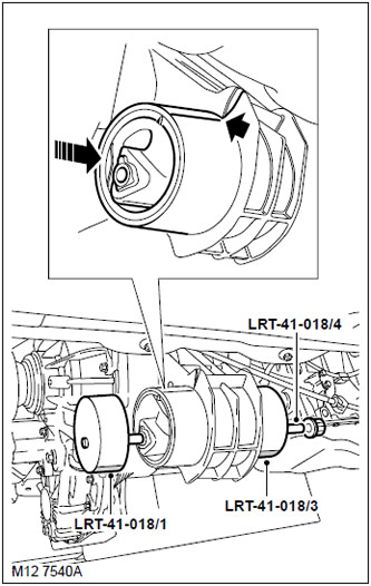
3. Position the new support at the rear of the transfer case and begin connecting. The support should move smoothly and the mounting marks should line up with each other.
NOTE: Transfer the mounting mark to the side of the support to assist in alignment.
4. Apply molybdenum grease to the center screw of the LRT-41-018/4 to install the support onto the transfer case. Start with the center screw fully out and when the support is about 75 percent in, reduce the length of the center screw by screwing it all the way into the LRT-41-018/1 plate. This will prevent the center screw of the LRT-41-018/4 from coming into contact with the transmission fluid and contaminating it.
CAUTION: Make sure the alignment indicator is in its lowest position.
5. Make sure that the support is installed without distortions. If necessary, restore parallelism by hitting the base plate with a wooden hammer.
6. Clean the vibration damper and mating surfaces.
7. Install the vibration damper and tighten the Torx screws to 23 N·m.
8. Clean the transfer case mating surface, mounting pins and holes for them.
9. Clean the input shaft and its mating surface.
10. Apply a thin coat of anti-seize lubricant to the shaft splines.
11. Install the transfer case and tighten the Torx screws to 43 N·m.
12. Connect the ventilation hose to the transfer case.
13. Connect the cable connector.
14. Remove the jack from under the transfer case.
15. Install silent blocks.
16. Connect the cross frame to the support, install the bolt and nut, but do not tighten it completely.
17. Raise the gearbox with a jack.
18. Install the cross frame, tighten the mounting screws and tighten them to a torque of 68 N·m.
19. Remove the jack from under the gearbox.
20. Tighten the nut and bolt securing the support to the cross frame to a torque of 100 Nm.
21. Install the heat shield and tighten its mounting nuts.
22. Install the rear propeller shaft.
DRIVE SHAFTS, REPAIR WORK, Cardan shaft - rear.
23. Install the front propeller shaft.
DRIVE SHAFTS, REPAIR WORK, Cardan shaft - front.
24. Pour the working fluid into the transfer case.
TRANSFER CASE, ADJUSTMENTS, Draining and filling the working fluid.
25. Install the fan viscous coupling.
COOLING SYSTEM: Td6, REPAIR WORK, Viscous fan clutch.
26. Replace the cover that covers the engine units.
TD6 ENGINE, REPAIR WORK, Upper engine casing.
Comments on this article