car logo Ford
car logo Volkswagen
car logo BMW
car logo Opel
car logo Audi
car logo Toyota
car logo Peugeot
English Русский
Български
Беларускі
Український
Српски
Hrvatski
Română
Polski
Slovenský
Magyar


Main
Freelander
Discovery
Range Rover
Defender
Contacts
Articles

Disassembling the transfer case components (Discovery 1)

 
  • Main
  • Discovery
  • Discovery 1
  • Transmission
  • Transfer case LT230T
  • Disassembling the transfer case components
 
        0  
Contents: Cross shaft housing ⇩ Front crankcase ⇩ Rear crankcase ⇩ Main crankcase ⇩ Transfer case drive gear housing ⇩ Intermediate gears ⇩ Secondary shaft drive gear assembly ⇩ Differential lock engagement housing ⇩ Differential ⇩

Cross shaft housing


1. If installed: loosen the neutral position switch lock nut and remove the switch.
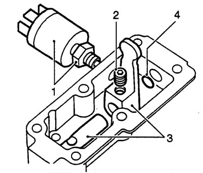
1. If installed: loosen the neutral position switch lock nut and remove the switch.


2. Loosen the screw securing the row shift lever.

3. Pull the rod out of the crankcase, remove the leash from the rod.

4. Remove and discard the sealing ring.

Front crankcase


1. Unscrew the seven bolts securing the differential lock side cover and remove the cover.
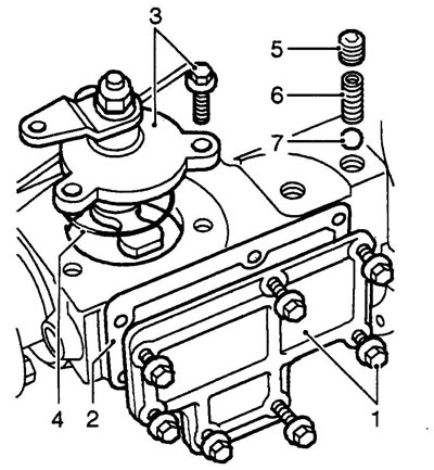
1. Unscrew the seven bolts securing the differential lock side cover and remove the cover.


2. Up to serial number 288709E: Remove and discard gasket.


3. Unscrew the three bolts securing the lock engagement lever housing, remove the housing and the lever together.

4. Remove the sealing ring from the lock housing. Do not reinstall the ring.

5. Unscrew the locking retainer plug.

6. Remove the retainer spring.

7. Use a magnet to remove the retainer ball.

Note: Place the retainer parts in a separate bag and label it. Do not confuse the shift lock and differential lock parts.


8. Compress the differential engagement fork spring, remove the retaining rings from both ends of the spring.
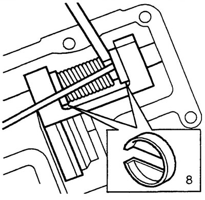
8. Compress the differential engagement fork spring, remove the retaining rings from both ends of…


9. Remove the lock engagement rod from the crankcase and remove the spring.
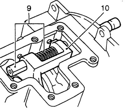
9. Remove the lock engagement rod from the crankcase and remove the spring.


10. Remove the lock engagement plug.

11. Hold the output shaft flange with the LRT-51-003 wrench.
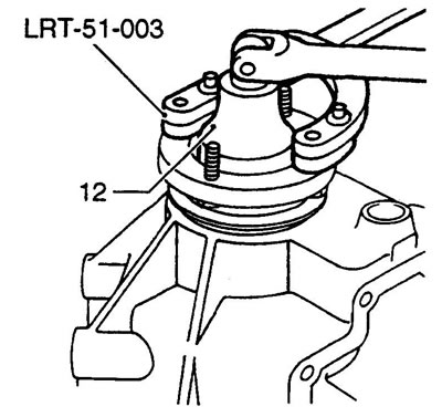


11. Hold the output shaft flange with the LRT-51-003 wrench.


12. Unscrew the flange mounting nut. Do not reinstall the nut.

13. Remove the steel and felt washers. Discard the felt washer.
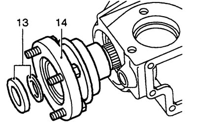
13. Remove the steel and felt washers. Discard the felt washer.


14. Remove the flange and mudguard, discard the flange.

Note: The spare parts supplied include a flange, mudguard and oil seal.


15. Knock out the output shaft from the front crankcase.
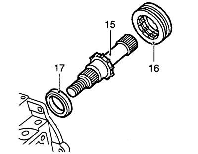
15. Knock out the output shaft from the front crankcase.


Note: If necessary, a hand press can be used by installing the LRT-370-11/2 stop between the press and the shaft.


16. Mark the installation position of the ratchet ring, remove the ring from the shaft.

17. Mark the installation position of the bearing spacer, remove the spacer.

18. Remove the output shaft seal from the crankcase. Be careful not to damage the oil seal seat.
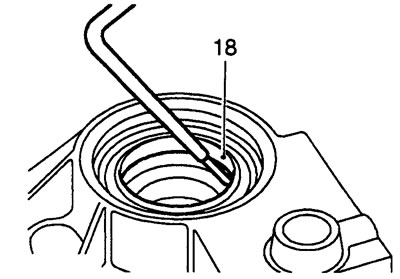
18. Remove the output shaft seal from the crankcase. Be careful not to damage the oil seal seat.


19. Remove the output shaft bearing retaining ring. Do not reinstall the retaining ring.
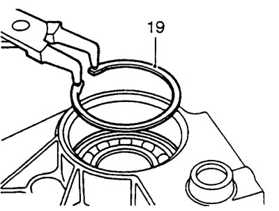
19. Remove the output shaft bearing retaining ring. Do not reinstall the retaining ring.


20. Place the front crankcase on two pieces of wood.
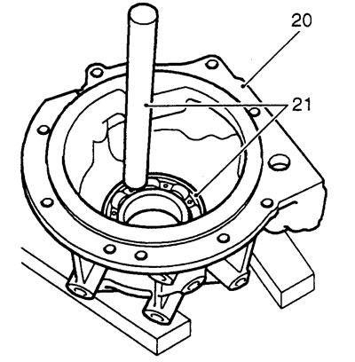
20. Place the front crankcase on two pieces of wood.


21. Use a bronze drift to knock out the output shaft bearing.


22. Turn the crankcase over.

23. Knock out the differential cup bearing race.
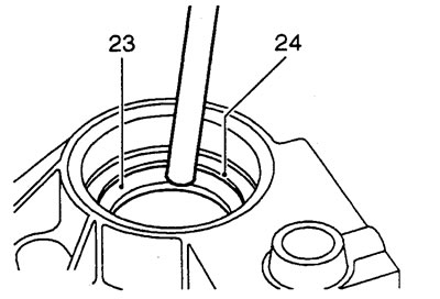
23. Knock out the differential cup bearing race.


24. Remove and mark the adjusting washers.

Rear crankcase


1. Hold the output shaft flange with the LRT-51-003 wrench.

2. Unscrew the flange mounting nut. Do not reinstall the nut.
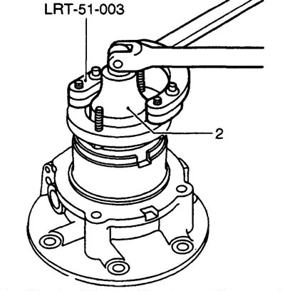
2. Unscrew the flange mounting nut. Do not reinstall the nut.


3. Remove the steel and felt washers. Discard the felt washer.
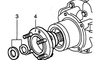
3. Remove the steel and felt washers. Discard the felt washer.


4. Remove the flange and retaining ring, discard the flange.


Note: The spare parts supplied include a flange and seal.


5. Carefully use a lever to remove the speedometer drive housing together with the driven gear from the crankcase.
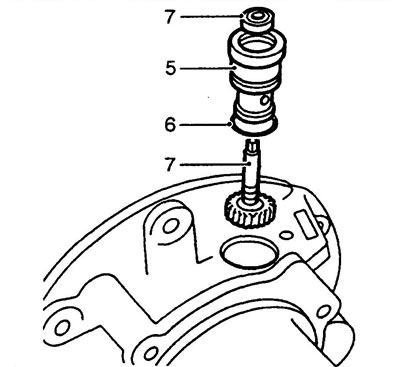
5. Carefully use a lever to remove the speedometer drive housing together with the driven gear from…


6. Remove and discard the sealing ring.

7. Remove the oil seal and remove the driven gear.

8. Install the rear crankcase on the press.

9. Install the LRT-370-11/2 stop between the press and the output shaft.
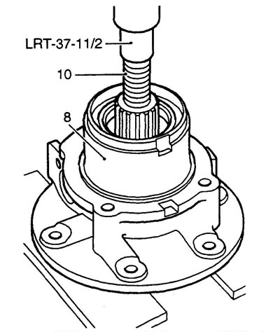
9. Install the LRT-370-11/2 stop between the press and the output shaft.


10. Press the output shaft.

11. Remove the spacer and speedometer drive pinion from the output shaft.
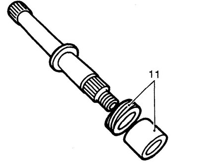
11. Remove the spacer and speedometer drive pinion from the output shaft.


12. Using a screwdriver inserted into the slot in the rear crankcase, remove the mud shield from the crankcase.
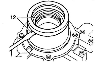


12. Using a screwdriver inserted into the slot in the rear crankcase, remove the mud shield from…


Caution: If the shield was deformed during removal, replace it.


13. Remove the output shaft seal from the crankcase. Be careful not to damage the oil seal seat.
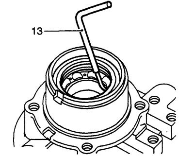
13. Remove the output shaft seal from the crankcase. Be careful not to damage the oil seal seat.


14. Remove the output shaft bearing retaining ring.
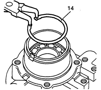
14. Remove the output shaft bearing retaining ring.


15. Place the rear crankcase on two pieces of wood.
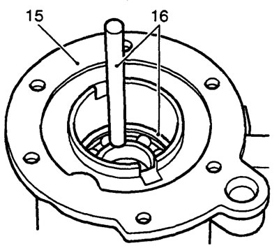
15. Place the rear crankcase on two pieces of wood.


16. Using a bronze drift, knock the output shaft bearing out of the crankcase.


Main crankcase


1. Place the main crankcase on two pieces of wood.

2. Using a bronze drift, knock the differential bearing race out of the crankcase.
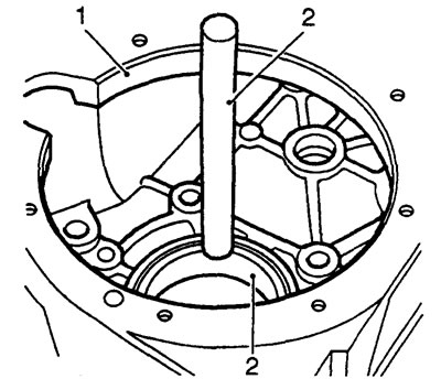
2. Using a bronze drift, knock the differential bearing race out of the crankcase.


3. Turn the crankcase over.

4. Using a bronze drift, knock the raceway of the transfer case drive gear bearing out of the crankcase.
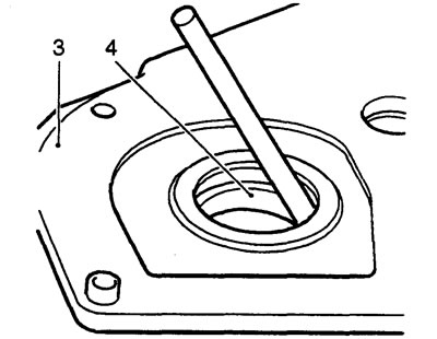
4. Using a bronze drift, knock the raceway of the transfer case drive gear bearing out of the…


Transfer case drive gear housing


1. Clamp the body in a vice with soft metal jaw spacers.

2. Using a bronze drift, knock the raceway of the transfer case drive gear bearing out of the housing.
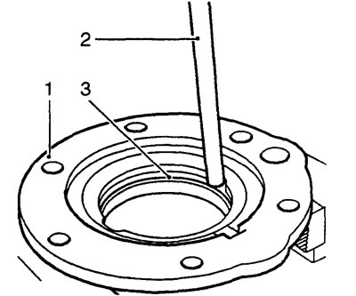
2. Using a bronze drift, knock the raceway of the transfer case drive gear bearing out of the…


3. Remove and mark the adjusting rings.

Intermediate gears


1. Clamp the idler gears in a vice with soft metal jaw spacers.

2. Use a bronze drift to knock the bearing race out of the gears.
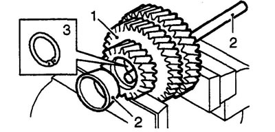
2. Use a bronze drift to knock the bearing race out of the gears.


3. Remove and discard the retaining ring.

4. Knock out the raceway of the second bearing.

Secondary shaft drive gear assembly


1. Clamp the LRT-99-002 puller in a vice.

2. Install the LRT-41-003 mandrel on the bearing to be removed.
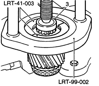
2. Install the LRT-41-003 mandrel on the bearing to be removed.


Note: The image shows the gearbox pinion of a Defender vehicle.


3. Install the secondary shaft on the puller and remove the bearings.

Differential lock engagement housing


1. Loosen the lock engagement lever shaft mounting nut. Do not reinstall the nut.

2. Remove the washer and lever.

3. Remove the leash and adjusting washer.

4. Remove and discard the sealing ring.
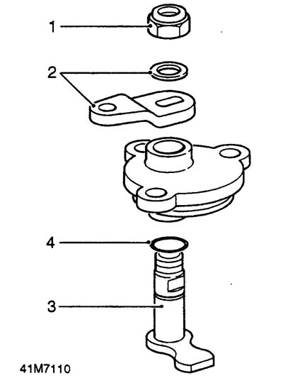
4. Remove and discard the sealing ring.


Differential


1. Clamp the differential in a vice with soft metal jaw pads.

2. Eliminate deformation of the bearing mounting nut punching areas.
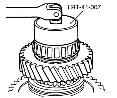
2. Eliminate deformation of the bearing mounting nut punching areas.


3. Use the LRT-41-007 key to unscrew the nut.

4. Secure the LRT-99-002 puller in a vice.

5. Install the LRT-41-001 mandrel on the rear bearing.

Note: This bearing is located near the threaded end of the differential shaft.


6. Install the differential in the puller stop, place the LRT-41-001 mandrel between the differential shaft and the puller pusher.
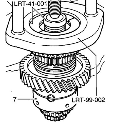
6. Install the differential in the puller stop, place the LRT-41-001 mandrel between the…


7. Press the differential off the bearing. Be careful not to drop the differential.

8. Discard the bearing.

9. Remove the sleeve and the gear of the top row, try not to touch the row shift clutch.
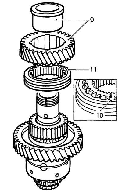
9. Remove the sleeve and the gear of the top row, try not to touch the row shift clutch.


10. Mark the relative position of the clutch and shift hub.

11. Remove the coupling.

12. Using a suitable puller and drift LRT-41-001, remove the hub and bottom row gear.
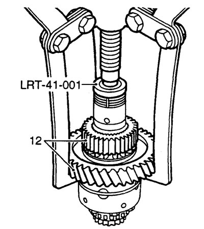
12. Using a suitable puller and drift LRT-41-001, remove the hub and bottom row gear.


13. Secure the LRT-99-002 puller in a vice.

14. Install the LRT-41-002 mandrel onto the front bearing.

Note: This bearing is located near the splined end of the differential shaft.
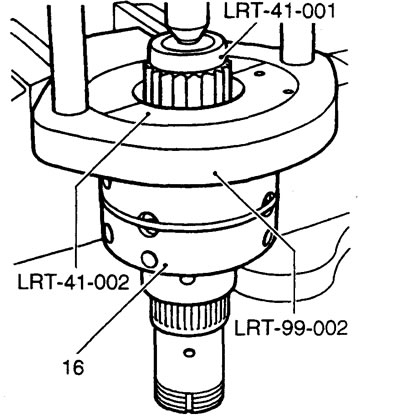

Note: This bearing is located near the splined end of the differential shaft.


15. Install the differential in the puller stop, place the LRT-41-001 mandrel between the differential shaft and the puller pusher

16. Press the differential off the bearing. Be careful not to drop the differential.

17. Discard the bearing.

18. Clamp the rear differential cup in a vice.

19. Mark the relative positions of the front and rear cups.

Note: The front cup is shorter than the back cup.


20. Unscrew the eight bolts securing the front cup and remove the front cup.
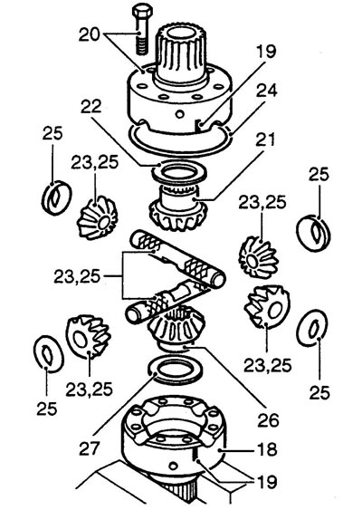
20. Unscrew the eight bolts securing the front cup and remove the front cup.


21. Mark the side gear of the front cup, remove the gear.

22. Remove the thrust washer. Do not reinstall the washer.

23. Mark the installation locations of the satellites and cross shafts.

24. Remove the retaining ring.

25. Remove the satellites and cross shafts, discard the plate thrust washers.

26. Mark the side gear of the lower cup, remove the gear.

27. Remove the thrust washer. Do not reinstall the washer.


This article is available at russian, bulgarian, belarusian, ukrainian, serbian, croatian, romanian, polish, slovak, hungarian
Article review: Konstantin Nazarov


Previous articles
LT230T Transfer Case Description
Removal and installation the transfer case
Shift lock solenoid, neutral switch (fitted on some vehicles)
Tightening torques for threaded connections (Nm)
Adjustment data (LT230T)
Special tool
LT230T Transfer Case Repair
Disassembling the transfer case

Current article
Disassembling the transfer case components

Next articles
Checking the details
Assembly of transfer case components
Transfer case assembly


Similar articles from Land Rover repair manuals:
• Transfer case breather Freelander 2 (2006-2014)
• Transfer case: models with KV6 engine Freelander 1 (1997-2006)
• Transfer case Range Rover 3 (2001-2012)
• Draining and filling the transfer case transmission fluid Defender 2007+ (2007-2016)

Comments on this article


No comments yet


How much will 23 + 11 =


Discovery 3 
  • General information
  • Using the manual
  • Precautionary measures
  • Service Information
  • Technique
  • Health protection
  • Road test
  • Identification codes
  • Jacking and lifting
  • Maintenance - diesel
  • Maintenance - petrol
  • Chassis
  • Suspension
  • Front suspension
  • Rear suspension
  • Wheels and tires
  • Dynamic suspension
  • Cardan shaft
  • Rear drive axle
  • Front drive axle
  • Front axle axles
  • Rear axle axles
  • Brake system
  • Parking brake
  • Hydraulic brake
  • Vacuum brake booster
  • Anti-lock braking system
  • Steering
  • Steering column
  • Power unit
  • Petrol engine 4.0L
  • Petrol engine 4.4L
  • Diesel engine 2.7L
  • Engine cooling
  • Fuel supply
  • Drive units
  • Launch system
  • Ignition system
  • Emission reduction
  • Air filtration
  • Fuel vapor control
  • Electronic control part
  • Car gearbox
  • Clutch
  • All-wheel drive systems
  • Transfer case
  • Exhaust system
  • Fuel tank and lines
  • Acceleration control
  • Electrical equipment
  • Climate control
  • Instruments and control lamps
  • Battery and charging system
  • Information system
  • Lighting and headlights
  • Power distribution
  • Electronic Function Group
  • Body and coating
  • Body elements
  • Interior and body trim
  • Mirrors and glasses
  • Seats
  • Instrument panel and console
  • Handles and locks
  • Windshield wipers and washers
  • Sunroof and bumpers
  • Safety system
  • Body repairs
  • Repair of front end elements
  • Repair of back elements
  • Side panel repair
  • Frame and body mount

Discovery 1 
  • General information
  • Technical specifications
  • Introduction to manual
  • Troubleshooting
  • Power unit
  • Diesel engine Tdi
  • Petrol engine V8i (3.9 l)
  • Petrol engine V8i (4.0 l)
  • Petrol engine Mpi
  • Reducing harmful emissions
  • Fuel system Tdi
  • Fuel system MFi
  • Fuel system SFi
  • Fuel system MPi (MEMS)
  • Cruise control
  • Cooling system (Tdi)
  • Cooling system (V8i)
  • Cooling system (MPi)
  • Exhaust system
  • Transmission
  • Clutch
  • Manual gearbox R380
  • Manual gearbox LT 77
  • Transfer case LT230T
  • Automatic gearbox
  • Cardan shaft
  • Rear axle
  • Front axle
  • Chassis
  • Steering system
  • Front suspension
  • Rear suspension
  • Brake system
  • Wheels and tires
  • Body and interior
  • Passive safety
  • Doors, locks and windows
  • Exterior body parts
  • Interior trim details
  • Seats
  • Electrical equipment
  • Heating and ventilation
  • Air conditioning
  • Windscreen wipers
  • Starting and charging system
  • Equipment and devices
  • Lighting and headlights


LRman.ru © 2013-2026 | Mobile version | Free Lander | Discovery | Range Rover | Defender | Contacts | | Sitemap |
Car repair and service instructions Land Rover: Freelander, Discovery, Range Rover, Defender
We use cookies to make pages load faster and provide a more user-friendly experience 🍪