Contents: Differential ⇩ Main crankcase ⇩ Secondary shaft drive gear housing ⇩ Secondary shaft pinion gear ⇩ Intermediate gears ⇩ Rear crankcase ⇩ Front crankcase ⇩ Cross shaft housing ⇩ Differential lock engagement housing ⇩
Differential
1. When installing, lubricate the parts with transmission oil.
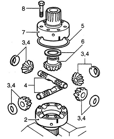
2. Clamp the rear differential cup in a vice.
Note: The back cup is longer than the front cup.
3. Install the satellites and new thrust washers in their places on the crosspiece shafts.
4. Install the crosspiece and satellites into the rear cup.
Note: It is important that the satellites and shafts are installed in their original positions. There is no need to install the side gears now.
5. Install the retaining ring.
6. Install the 1.05mm front side gear thrust washer and side gear into the front differential cup.
Note: The thrust washer thickness of 1.05 mm is the minimum possible.
7. Install the front cup onto the rear cup, aligning the relative position marks.
8. Tighten the differential cup mounting bolts in a diagonal sequence to a torque of 60 N·m.
9. Insert the output shaft into the front cup, check the free rotation of the gears.
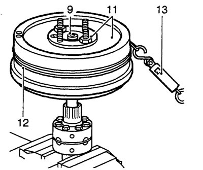
10. Place the new flange on the shaft (do not install the fastening nut).
Note: The flange and seal are supplied as a spare part.
11. Install the parking brake drum on the flange and secure it with two nuts.
12. Wrap the cord around the drum and attach a spring dynamometer to the free end of the cord.
The original text can be found at [LRman.ru]
13. Pull the cord through the dynamometer and read the dynamometer readings.
Note: When installing old differential gears, rotation should be smooth; when installing new gears, jerking may be felt.
14. With the correct selection of the thrust washer, the differential turning force should be equal to: new gears - 1.72 kg old gears - 0.45 kg.
15. If the scrolling force is not equal to the specified one, perform the following operations:
16. Remove the output shaft together with the parking brake drum.
17. Loosen the differential cup mounting bolts.
18. Remove the front cup.
19. Remove the side gear and thrust washer
20. Select a thrust washer of a different thickness.
Note: washers are available in thicknesses from 1.05 to 1.45 mm in 0.1 mm increments.
21. Install the side gear and new thrust washer into the front cup.
22. Install the front cup onto the rear cup, aligning the relative position marks.
23. Tighten the differential cup mounting bolts in a diagonal sequence to a torque of 60 N·m.
24. Insert the output shaft with the brake drum into the front cup, check the free rotation of the gears and the scrolling force.
25. If necessary, repeat the described operations again.
26. Remove the brake drum and output shaft.
27. Loosen the differential cup mounting bolts.
28. Remove the front cup, side gear and thrust washer.
Caution: Store the selected thrust washer together with the gear.
29. Remove the retaining ring.
30. Remove the satellites, thrust washers and cross shafts.
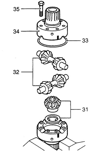
31. Install the 1.05mm rear side gear thrust washer and side gear into the rear differential cup.
32. Install the satellites, thrust washers and cross shafts.
Note: It is important that the satellites and shafts are installed in their original positions.
33. Install the retaining ring.
34. Install the front cup according to the relative position marks.
Note: Do not install the front side gear into the front cup at this time.
35. Install and tighten the bolts in a diagonal sequence to a torque of 60 Nm.
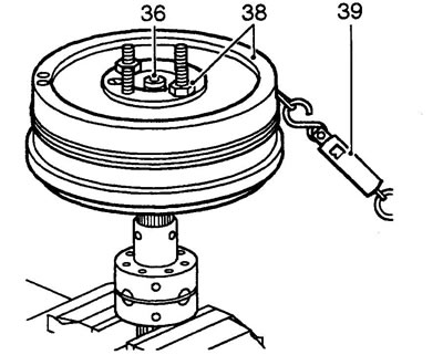
36. Turn the differential over. Insert the output shaft into the rear cup. Check the freedom of rotation of the gears.
37. Install a new flange onto the output shaft splines (do not install the fastening nut).
Note: The flange and seal are supplied as a spare part.
38. Install the parking brake drum on the flange and secure it with two nuts.
39. Check the scrolling force using the same method as for the front cup.
40. If everything is normal, write down the final result.
41. Disassemble the differential and install the front side gear and its thrust washer.
42. Install the front differential cup according to the relative position marks.
43. Tighten the differential cup mounting bolts in a diagonal sequence to a torque of 60 Nm.
44. After assembly, insert any of the output shafts into the differential, install the parking brake drum and check the total cranking force: new gears - 3.44 kg old gears - 0.90 kg.
45. Secure the differential in a vice by the rear cup.
46. Using the LRT-41-008 mandrel, install the new front bearing.
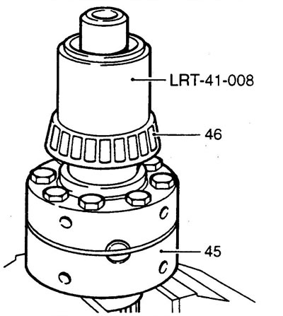
47. Clamp the differential in a vice by the front cup.
48. Install the gear of the lower row with the engagement splines towards the threaded part.
Note: To ensure the gear fits completely, use a piece of pipe of the appropriate size.
49. Install the shift clutch hub so that the mark made during removal is directed towards the threaded part.
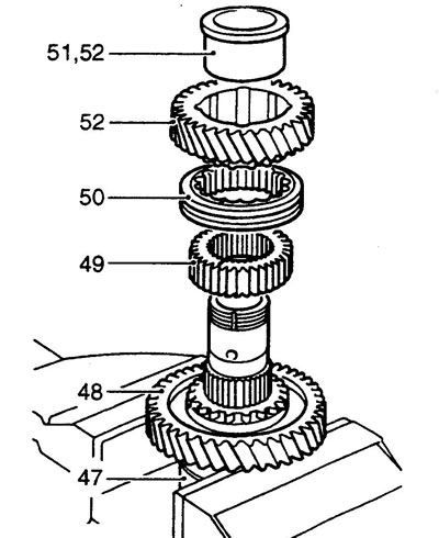
50. Install the shift clutch, aligning the relative position marks on the clutch and hub.
51. Install the sleeve on the top row gear so that the flange of the sleeve is directed away from the engagement splines.
52. Install the top row gear with the flange of the sleeve towards the threaded part.
53. Using the LRT-41-008 mandrel, install the new rear bearing.
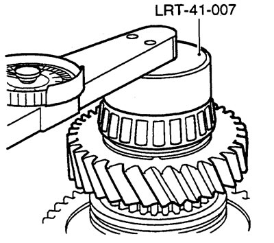
54. Use the LRT-41-007 wrench to tighten the bearing mounting nut.
Note: there is no need to secure the nut with a punch now.
55. Slide the clutch and shift hub away from the bottom row gear.
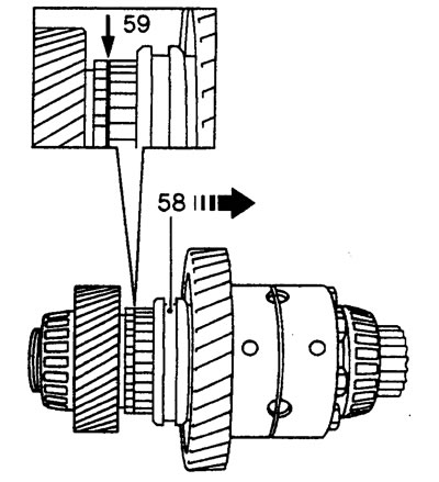
56. Measure the clearance between the bottom row gear and the shift clutch hub.
Permissible gap: 0.05 - 0.15 mm.
57. If the clearance is outside the permissible limits, install a new bottom row gear and/or hub, recheck the clearance.
58. Slide the clutch and shift hub away from the top row gear.
59. Measure the clearance between the top row gear and the shift clutch hub.
Permissible gap: 0.05 - 0.15 mm.
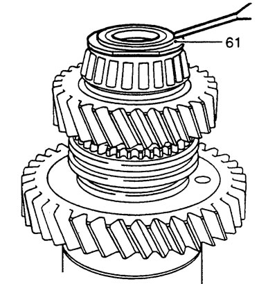
60. If the clearance is outside the permissible limits, install a new top row gear and/or hub, recheck the clearance.
61. Using a spherical punch, mark the bearing mounting nut skirt against the recess on the differential shaft.
Main crankcase
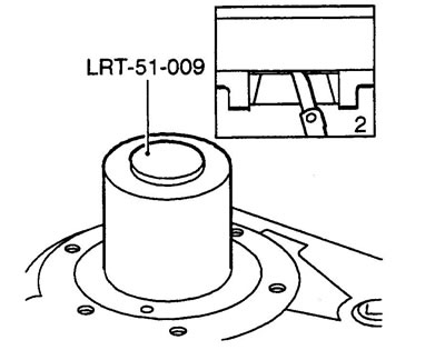
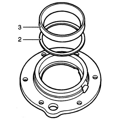
1. Using the LRT-51-009 tool, install the raceway of the new rear differential bearing into the crankcase.
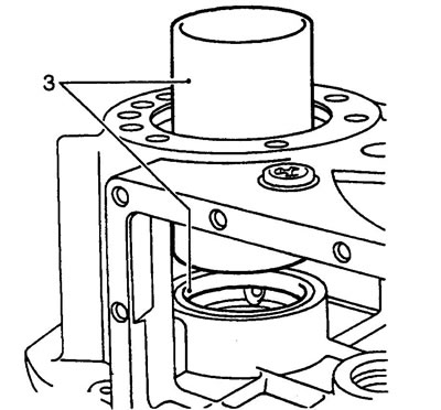
2. Using a parallel block and a flat feeler gauge, measure the recession depth of the treadmill: the treadmill should be installed to a depth of 1 mm.
3. Using a suitable drift, install the raceway of the new secondary shaft pinion bearing into the crankcase.
Attention: treadmills must be perpendicular to the seat axis.
4. Lubricate the new secondary shaft seal with transmission oil.
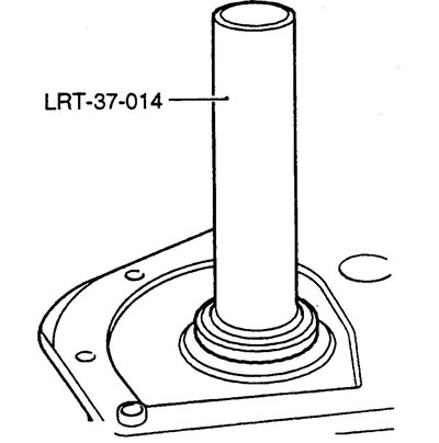
5. Turn the crankcase over. Using the LRT-37-014 mandrel, install the secondary shaft seal with the sealing lip facing inward.
Secondary shaft drive gear housing
1. Measure and record the thickness of the original shim.
2. Install the original washer into the housing.
3. Using a suitable drift, install the raceway of the new secondary shaft pinion bearing into the housing.
Attention: the treadmill must be perpendicular to the axis of the seat.
Secondary shaft pinion gear
1. Lubricate the new bearing with transmission oil.
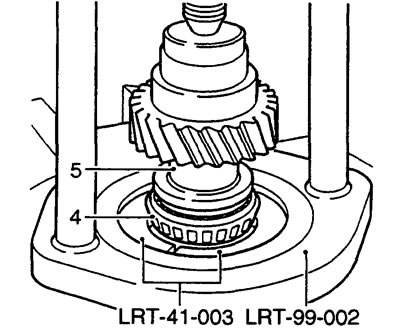
2. Secure the LRT-99-002 puller in a vice.
3. Install the LRT-41-003 mandrel into the puller.
4. Place the new bearing on the mandrel.
Note: The smaller diameter of the bearing must face the mandrel.
5. Insert the secondary shaft into the bearing, press the shaft into the bearing.
6. Install the second bearing in a similar manner.
Intermediate gears
1. Lubricate the new bearing and its raceways with transmission oil.
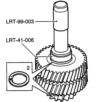
2. Install new retaining rings on the intermediate gears. Check that the rings are seated correctly.
3. Using tools LRT-99-003 and LRT-41-006, install the bearing races until they rest against the retaining rings.
4. Install bearings and gears.
Rear crankcase
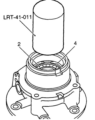
1. Heat the rear crankcase to 100°C.
2. Using the LRT-41-011 mandrel, install the output shaft bearing.
3. Cool the crankcase with compressed air.
4. Install the bearing retaining ring. Check that the ring is seated correctly in the groove.
5. Lubricate the output shaft seal with transmission oil.
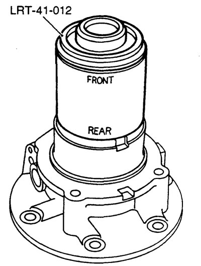
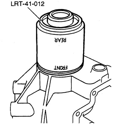
6. Using the LRT-41-012 tool, install the oil seal.
Note: When installing the oil seal, use the end of the drift marked REAR.
7. Check for contact between the oil seal and the retaining ring.
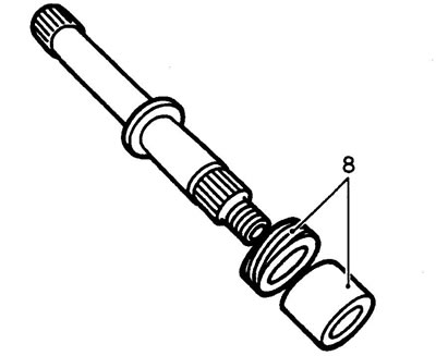
8. Install the speedometer drive gear and spacer onto the output shaft.
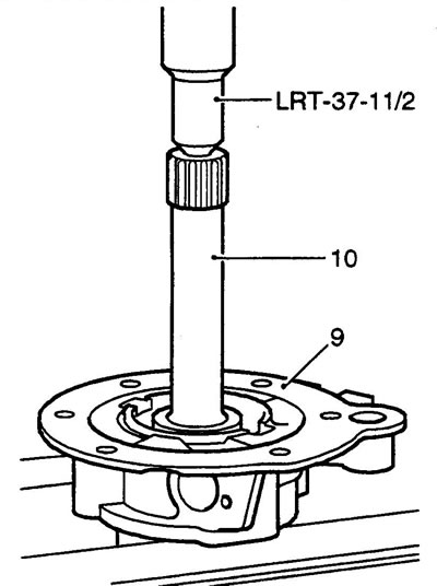
9. Install the rear crankcase on the press shelf.
10. Insert the threaded end of the output shaft into the bearing.
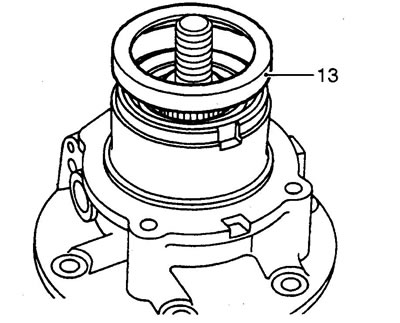
11. Install the LRT-37-11/2 stop between the press pusher and the shaft.
12. Press the shaft into the bearing.
13. Install the mudguard with the open end towards the oil seal.
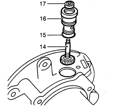
Caution: Do not install the output shaft flange at this time.
14. Install the speedometer drive driven gear into the rear housing. Engage the gears.
15. Install a new sealing ring on the speedometer drive housing and lubricate it with transmission oil.
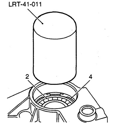
16. Install the speedometer drive housing into the rear crankcase.
17. Lubricate the driven gear oil seal with transmission oil and install it with the sealing lip towards the housing.
Front crankcase
1. Heat the front crankcase to 100°C.
2. Using the LRT-41-011 mandrel, install the output shaft bearing.
3. Cool the crankcase with compressed air.
4. Install the bearing retaining ring. Check that the ring is seated correctly in the groove.
5. Lubricate the output shaft seal with transmission oil.
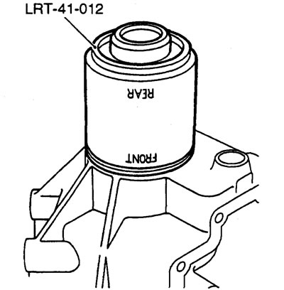
6. Using the LRT-41-012 tool, install the oil seal.
Note: When installing the oil seal, use the end of the drift marked FRONT.
7. Measure and record the thickness of the original front differential bearing adjusting shim.
8. Install the original adjusting washer into the front crankcase.
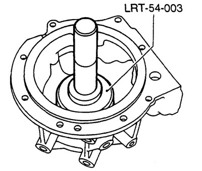
9. Using the LRT-54-003 tool, install the raceway of the new front differential bearing.
10. Install the bearing spacer on the output shaft with the chamfer facing the threaded part of the shaft.
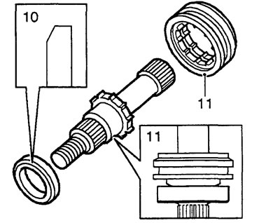
11. Install the ratchet ring with the flange towards the splined part of the shaft.
12. Using a bronze drift, drive the shaft into the bearing.
Caution! Do not proceed with further assembly of the front crankcase at this time.
Cross shaft housing
1. Lubricate the cross shaft and new O-ring with transmission oil.
2. Insert the cross shaft into the housing, place the row shift lever onto the shaft.
3. Install the sealing ring on the shaft and insert the shaft into the housing plug.
4. Slide the sealing ring toward the end of the shaft.
5. Align the hole in the leash with the recess on the shaft.
6. Apply Loctite 290 locking adhesive to the threads of the leash mounting screw and tighten the screw.
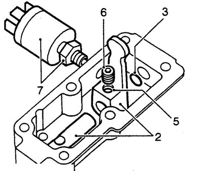
7. If installing: Install the neutral position switch, tighten the lock nut.
Differential lock engagement housing
1. Lubricate the O-rings of the locking lever and its housing with transmission oil.
2. Install the leash into the housing.
3. Set the leash lever to the position shown in the figure.
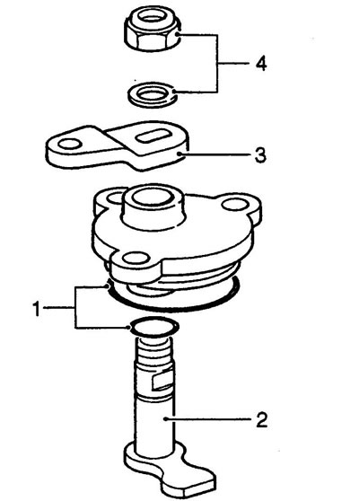
4. Install the washer and new lever mounting nut. Tighten the nut to a torque of 15 Nm.
Comments on this article