2. Drain the oil from the gearbox and replace the drain plug.
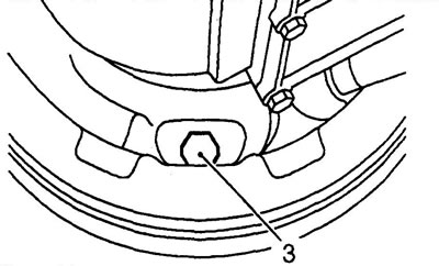
3. Loosen the parking brake shoe adjustment bolt.
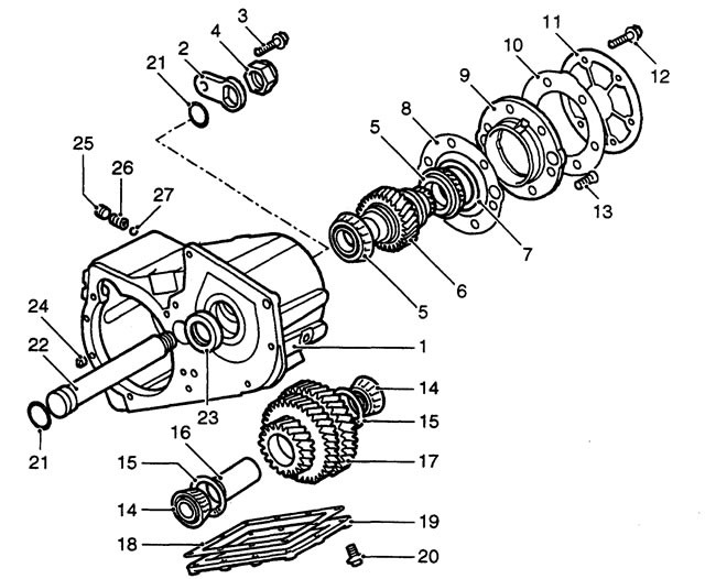
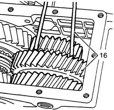
Main crankcase details. 1 - main crankcase, 2 - retaining plate, 3 - bolt, 4 - intermediate shaft nut, 5 - secondary shaft pinion bearings, 6 - secondary shaft pinion *, 7 - adjusting washer, 8 - gasket **, 9 - secondary shaft pinion bearing housing, 10 - gasket **, 11 - cover *, 12 - bolt, 13 - bearing housing screw, 14 - intermediate gear bearings, 15 - retaining rings, 16 - deformable spacer, 17 - intermediate gears, 18 - gasket **, 19 - lower cover, 20 - bolt, 21 - intermediate shaft seal ring, 22 - intermediate shaft, 23 - secondary shaft oil seal, 24 - guide pin, 25 - plug row shift lock, 26 - spring, 27 - row shift lock ball, * - Defender drive pinion and Discovery cover shown, ** - up to serial number 288709E.
4. Loosen the parking brake drum mounting screw and remove the drum.
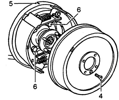
Note: On early transfer case models, the drum is secured with two screws.
5. Mark the relative positions of the rear crater of the gearbox and the parking brake support disc.
6. Unscrew the four bolts securing the support disk and remove the support disk.
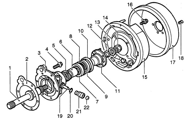
Rear crankcase and parking brake parts. 1 - rear output shaft, 2 - gasket *, 3 - rear crankcase, 4 - bolt, 5 - speedometer drive pinion, 6 - spacer, 7 - bearing, 8 - retaining ring, 9 - oil seal, 10 - mud shield, 11 - output shaft flange, 12 - felt washer, 13 - steel washer, 14 - nut, 15 - parking brake support disc, 16 - bolt, 17 - parking brake drum, 18 - screw, 19 - speedometer drive pinion, 20 - sealing ring, 21 - speedometer drive housing, 22 - oil seal.
7. Loosen the vehicle speed sensor mounting screw (if installed).
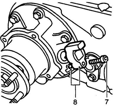
8. Remove the speed sensor and discard the sealing ring.
9. Unscrew the six bolts securing the bottom cover and remove the cover.
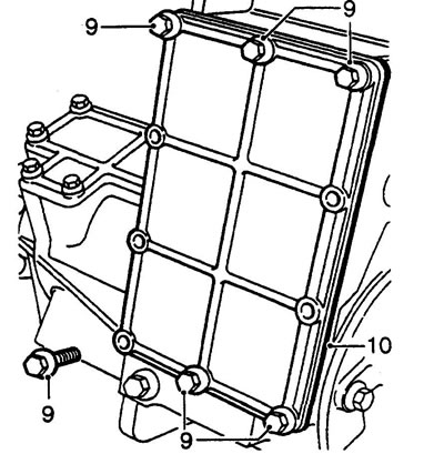
10. Up to serial number 288709E: Remove and discard gasket.
11. Straighten the skirt of the intermediate shaft mounting nut, unscrew and discard the nut.
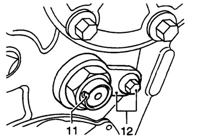
12. Loosen the retaining plate mounting bolt and remove the plate.
13. Using a bronze drift, knock out the intermediate shaft (strike from the side of the threaded part of the shaft).
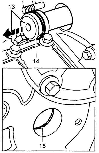
14. Remove and discard the intermediate shaft seal ring.
15. Remove and discard the main crankcase seal ring.
16. Tie the intermediate shaft gears with suitable wire and, with the help of an assistant, remove the gears from the main crankcase.
17. Remove and discard the two intermediate shaft tapered bearings.
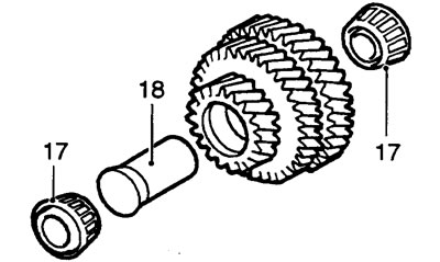
18. Remove and discard the deformable spacer.
Caution: Do not remove the bearing races at this time.
19. Remember the installation location of the speedometer cable support clip mounting stud, unscrew the five bolts and one nut securing the cover. Remove the clip.
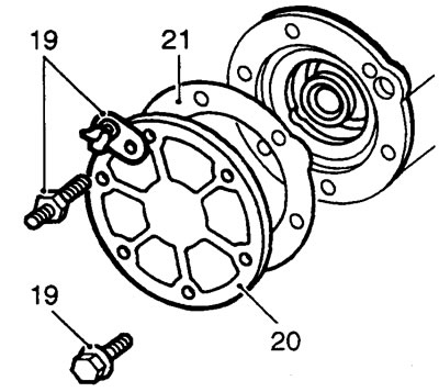
20. Remove the cover.
21. Up to serial number 288709E: Remove and discard gasket.
22. Loosen the two screws securing the transfer case drive gear bearing housing.
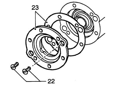
23. Up to serial number 288709E: Remove bearing housing and discard gasket.
Caution: Do not remove the drive gear bearing races at this time.
24. From serial number 288709E: Remove the bearing housing.
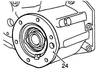
Caution: Do not remove the drive gear bearing races at this time.
25. Remove the drive gear together with the bearings.
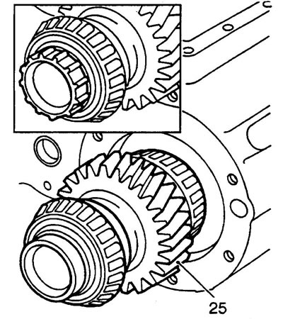
Note: On Defender models the pinion gear has an additional ratchet ring (insert in the picture).
26. Knock out the secondary shaft seal from the main crankcase. Do not reinstall the seal.
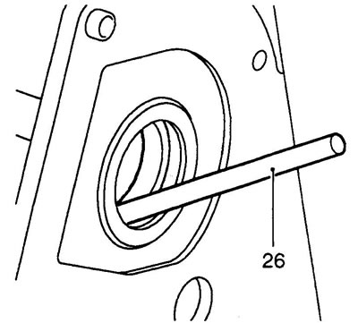
Attention: do not remove the bearing races of the drive gear from the secondary shaft at this time.
The text of the article was taken from the website [www.lrman.ru]
27. Unscrew the six bolts securing the cross shaft housing.
28. Remove the cross shaft housing.
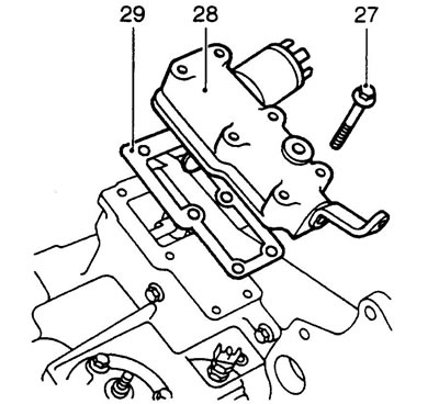
29. Up to serial number 288709E-, remove and discard the gasket.
Caution: Do not disassemble the cross shaft housing further at this time.
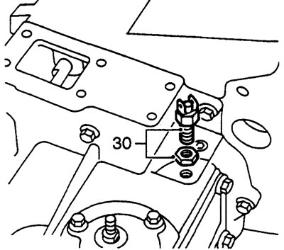
30. Loosen the lock nut and remove the differential lock indicator switch from the front housing.
31. Unscrew the eight bolts securing the front crankcase, remember the installation locations of the long bolts.
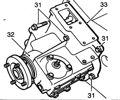
32. Remove the front crankcase.
Note: Installation is carried out using guide pins.
33. Up to serial number 288709E: Remove and discard gasket.
Caution: Do not disassemble the front crankcase further at this time.
34. Unscrew the five rear crankcase mounting bolts, remember the bolt installation locations. Remove two washers.
35. Remove the rear crankcase.
Note: Installation is carried out using guide pins.
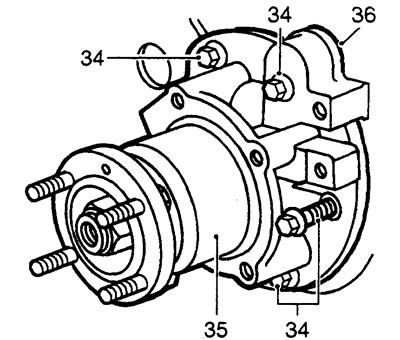
36. Up to serial number 288709E: Remove and discard gasket.
Caution: Do not disassemble the rear crankcase further at this time.
37. Unscrew the plug of the row shift rod retainer.
38. Remove the retainer spring.
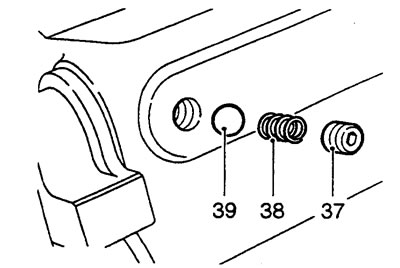
39. Using a magnet, remove the retainer ball. Note: Place the retainer parts in a separate bag and label it. Do not confuse the shift lock and differential lock parts.
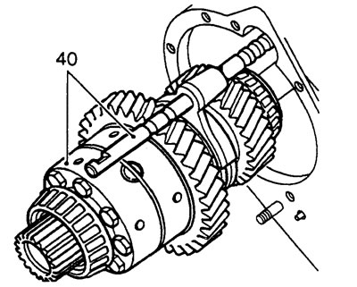
40. Remove the differential together with the rod and the row shift fork.
Comments on this article