Contents: Adjusting the preload of the…⇩ Adjusting the differential bearing…⇩ Front crankcase ⇩ All models ⇩ Rear crankcase ⇩ Intermediate gears ⇩ Adjusting the intermediate shaft…⇩ All models ⇩ Bottom cover ⇩ Row shift rod lock ⇩ Adjusting the position of the lock…⇩ Parking brake ⇩
During installation, lubricate all components and parts with transmission oil.
Adjusting the preload of the secondary shaft pinion bearings
1. Install the pinion assembly into the main crankcase.
2. Up to serial number 288709E: Place the pinion bearing housing gasket on a dry surface of the main crankcase.
3. All models: Install the pinion bearing housing, hand tighten the five bolts and one nut.
4. Install the LRT-41-005 tool onto the secondary shaft splines.
5. Wrap the cord around the device. Attach a spring dynamometer to the free end of the cord.
6. Pull the cord through the dynamometer and read the readings.
7. Normally, the preload should be equal to 2.26 - 9.0 kg.
8. If the preload is not as specified, remove the bearing housing.
9. Carefully knock the bearing race out of the housing and remove the adjusting washer.
Please note: If the treadmill is damaged, the entire bearing assembly must be replaced.
10. Install the adjusting washer of the required thickness.
Note: Adjusting shims are available in 0.025 mm increments. Installing a thicker shim increases bearing preload.
11. Reinstall the adjusting washer and bearing race and check the preload again.
12. Write down the final result.
Caution: Without removing the fixture, tighten the mounting bolts or apply sealant to the bearing housing when determining the idler gear bearing preload.
Adjusting the differential bearing preload
1. Install the differential shift rod and fork onto the differential. The fork must engage with the shift clutch.
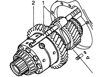
4. All models: Install the front crankcase, check for proper engagement of the output shaft with the differential and ratchet ring.
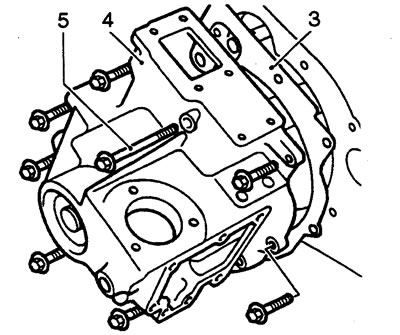
5. Install and hand tighten the eight mounting bolts. The longest bolts should go through the shift housing.
6. Engage the upper or lower range of the transfer case.
7. Wrap the cord around the splined part of the shift hub and attach a spring loader to the free end of the cord.
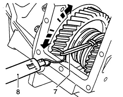
8. Pull the cord through the dynamometer and determine the differential cranking force.
9. Everything is normal if the scrolling force is within the range of 1.36 - 4.53 kg.
10. If the cranking force is outside the permissible limits, remove the front crankcase.
11. Remove the output shaft, ratchet ring and bearing spacer.
12. Carefully knock the bearing race out of the crankcase and remove the adjusting washer.
Please note: If the treadmill is damaged, the entire bearing assembly must be replaced.
13. Install the adjusting washer of the required thickness.
Note: Adjusting shims are available in 0.025 mm increments. Installing a thicker shim increases bearing preload.
14. Reinstall the adjusting washer and bearing race and check the preload again.
15. Install the output shaft, ratchet ring and bearing spacer.
16. Repeat the preload checking procedure.
17. After completing the support of the adjusting washer, remove the front crankcase.
18. Up to serial number 288709E: Leave the gasket on the main crankcase.
Front crankcase
1. Up to serial number 288709E: Apply Hylomar RTV 102 sealant to the front crankcase mating surface.
All models
2. Install the front crankcase, check for engagement of the output shaft with the differential and ratchet ring.
3. Apply Loctite 290 locking adhesive to the threads of the mounting bolts.
4. The longest bolts should go through the shift housing.
5. Tighten the mounting bolts in a diagonal sequence to a torque of 26 N·m.
6. Install the new shaft flange, felt and steel washers.
7. Screw on the new flange mounting nut.
8. Hold the flange with the LRT-51-003 key.
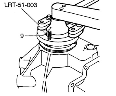
9. Tighten the mounting nut to 47 Nm.
10. Compress the spring of the lock engagement fork, install the fork.
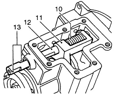
11. Insert the fork pins into the groove of the ratchet ring.
12. Install the lock engagement rod. The end of the shaft must fit into the cutout in the crankcase.
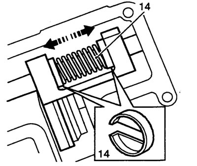
13. Turn the rod so that the two surfaces for installing the spring clips are located at right angles to the mating surface of the cover.
14. Compress the spring and install clips on both sides. Make sure the spring fits into the clips.
15. Install the ball and retainer spring.
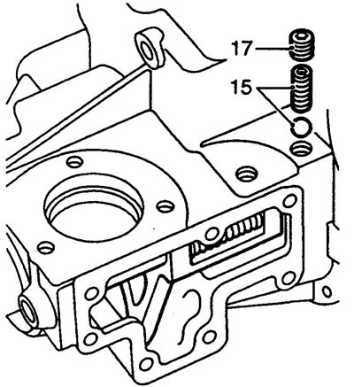
16. Apply Loctite 290 locking adhesive to the threads of the locking plug.
17. Screw the cap in until it stops and then unscrew it two full turns.
18. Check that the sealing ring is correctly installed on the lock engagement housing.
19. Install the lock housing by engaging the leash and the lock engagement rod.
20. Apply Loctite 290 locking adhesive to the threads of the mounting bolts.
21. Install the bolts and tighten them to 25 Nm.
22. Turn the lock on and off. Check that the rod is securely locked in both positions. To adjust the operation of the retainer, turn the plug to change the preload of the retainer spring.
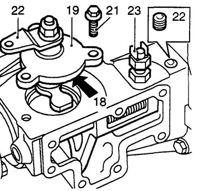
23. Install the differential lock indicator switch.
Caution: Do not tighten the switch lock nut before adjusting the switch position.
24. Up to serial number 288709E: Lubricate the gasket with grease, place the gasket on the front crankcase.
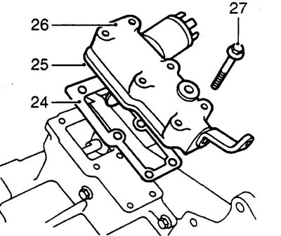
25. From serial number 288709E: Apply Hylomar RTV102 sealant to the switch housing seat.
26. Install the row shift housing by engaging the pin and the shift rod.
27. Install the six mounting bolts and tighten them to 25 Nm.
Rear crankcase
1. Up to serial number 288709E: Install a dry gasket onto the main crankcase.
2. From serial number 288709E: Apply Hylomar RTV102 sealant to the rear crankcase seat.
3. Install the rear housing by engaging the splines of the output shaft and differential.
4. Apply Loctite 290 locking adhesive to the threads of the headrest bolts.
5. Install washers on the remaining two bolts and apply Loctite 290 locking adhesive to the threads.
6. Tighten the rear crankcase mounting bolts in a diagonal sequence to a torque of 25 Nm.
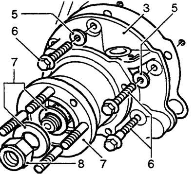
7. Install the new shaft flange, felt and steel washers.
8. Screw on the new flange mounting nut.
9. Hold the flange with the LRT-51-003 key.
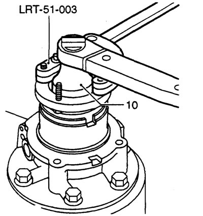
10. Tighten the mounting nut to a torque of 47 N·m.
11. If installing: Install a new O-ring onto the vehicle speed sensor and lubricate the O-ring with transmission fluid.
12. Install the vehicle speed sensor.
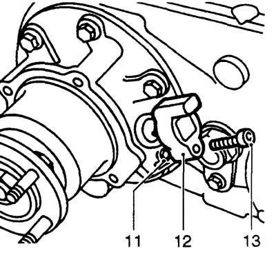
13. Tighten the sensor mounting bolt (internal hexagon).
Intermediate gears
1. Install the deformable bushing and bearings into the gear block.
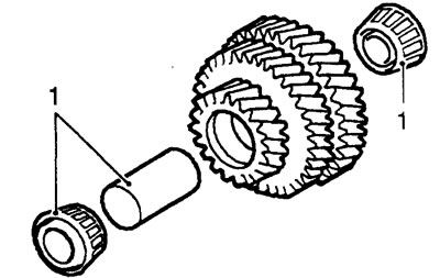
2. Suspend the gear block on a suitable wire and, with the help of an assistant, place the gears into the main crankcase. Engage the intermediate gears with the pinion gear and differential gears.
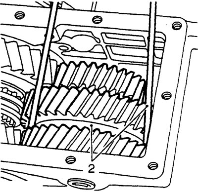
Note: Do not remove the support wire now.
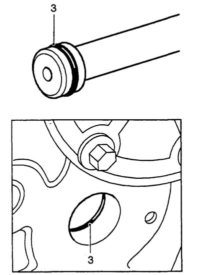
3. Lubricate the new main crankcase and intermediate shaft sealing rings with transmission oil, install the rings on the intermediate shaft and into the crankcase.
4. Raise the intermediate gear block until the LRT-41-004 process shaft can be installed into the main crankcase and gear block. Install the process shaft.
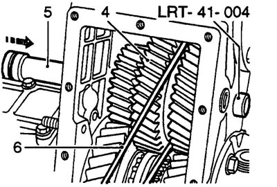
5. Push out the process shaft with the intermediate shaft, install the intermediate shaft in place.
Caution: Make sure the sealing ring in the main crankcase remains in place.
6. Remove the support wire.
7. Turn the intermediate shaft until the retaining plate can be installed.
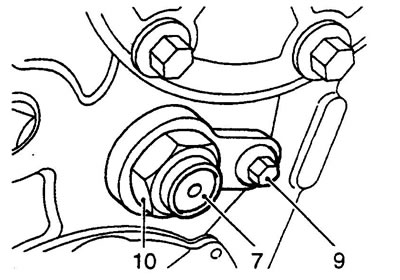
8. Apply Loctite 290 locking adhesive to the threads of the retaining plate.
9. Install the retaining plate bolt and tighten it to 25 Nm.
10. Install and hand tighten the intermediate shaft mounting nut.
Note: Do not pry the nut skirt now.
Adjusting the intermediate shaft bearing preload
1. Shift the transfer case into neutral.
2. Check that the LRT-41-005 tool is correctly installed on the secondary shaft. Wrap the cord around the device and connect a spring dynamometer to the free end of the cord.
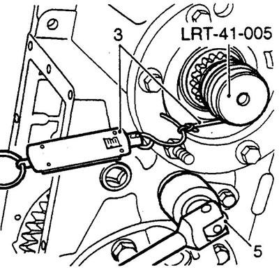
3. Pull the cord through the dynamometer and read the dynamometer readings.
4. Normally, the preload of the intermediate shaft bearings should increase the preload on the secondary shaft by 2.1 - 5.3 kg relative to the previously made adjustments.
5. To increase preload, tighten the intermediate shaft nut in small increments, checking the overall preload each time.
Caution: Do not increase preload excessively. If the maximum permissible preload value is exceeded, replace the intermediate gear bushing.
6. After completing the adjustment, pin the skirt of the intermediate shaft mounting nut.
7. Remove the LRT-41-005 tool from the secondary shaft.
8. Up to serial number 288709E: Install and tighten the two secondary shaft pinion housing retaining screws.
9. Remove the bearing housing mounting bolts.
10. From serial number 288709E: remove the bearing housing, apply Hylomar RTV 102 sealant to the mating surface, reinstall the housing and tighten the two mounting screws.
All models
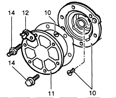
11. Install the bearing housing cover onto the gasket, aligning the holes for installing the bolts.
12. Install the clip onto the hairpin.
13. Apply Loctite 290 locking adhesive to the bolt and nut threads.
14. Tighten the cover fasteners in a diagonal sequence to a torque of 25 Nm.
Bottom cover
1. Up to serial number 288709E: Install a new dry cover gasket.
2. From serial number 288709E', apply Hylomar RTV 102 sealant to the mating surface of the cover.
3. Install the bottom cover.
4. Apply Loctite 290 locking adhesive to the threads of the cover mounting bolts.
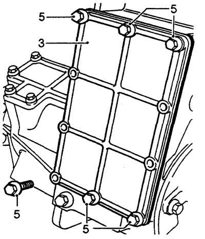
5. Tighten the cover mounting bolts in a diagonal sequence to a torque of 25 Nm.
Row shift rod lock
1. Install the ball and detent spring.
2. Apply Loctite 290 locking adhesive to the threads of the locking plug.
3. Screw the cap in until it stops and then unscrew it two full turns.
4. Alternately engage and disengage the transfer case rows. Check the reliability of the latch. If necessary, change the preload of the retainer spring by turning the plug.
Adjusting the position of the lock indicator switch
1. Engage the differential lock.
2. Connect the test lamp and battery to the switch terminals.
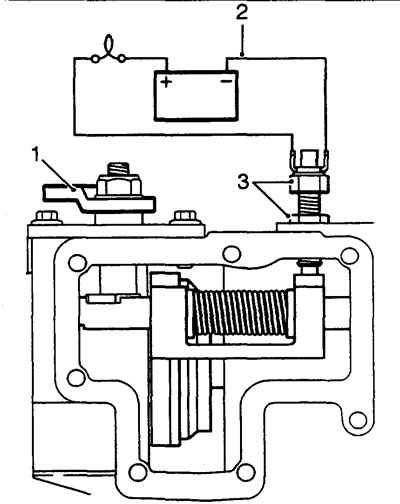
3. Turn the switch until the lamp lights up. From this position, turn the switch another half turn and tighten the lock nut.
4. Disengage the differential lock.
5. Remove the test lamp.
6. Up to serial number 288709E: Lubricate the lock housing side cover gasket with grease.
7. From serial number 288709E: Apply Hylomar RTV 102 sealant to the mating surface of the lock housing side cover.
8. Install the side cover and tighten the mounting bolts to 25 Nm.
Parking brake
1. Apply Hylomar RTV 102 sealant to the rear housing mating surface.
2. Install the parking brake support disc according to the relative position marks made during removal.
3. Install the four mounting bolts and tighten the bolts to a torque of 70 Nm.
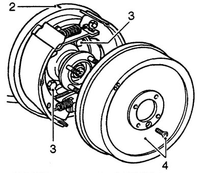
4. Install the brake drum, tighten the mounting screw.
Note: On early models, the drum was secured with two screws.
Comments on this article