Contents: Intermediate shaft and gears ⇩ Secondary shaft pinion gear ⇩ Cross shaft and its housing ⇩ Front housing and differential lock…⇩ Rear crankcase ⇩ Main crankcase ⇩ Differential ⇩
1. Wash all parts, remove any remaining sealant and locking adhesive.
Note: It is not recommended to use a tap to clean threaded holes.
2. On models up to part number 288709E, remove any remaining old gaskets from the mating surfaces.
3. Check for cracks or other damage to the crankcases.
4. Replace all defective parts.
Intermediate shaft and gears
1. Check the gear teeth for wear, chips or cracks.
2. Check the shaft threads for wear and condition.
Secondary shaft pinion gear
1. Check the gear teeth for wear, chips or cracks.
2. Defender only: Check the ratchet ring teeth. There should be no rounding or cracks in the teeth.
Cross shaft and its housing
1. Check the shaft and housing holes for wear.
2. Check that the plug is securely installed. If there are signs of leaks or corrosion, replace the plug. Installation is carried out using Loctite 326 glue.
3. Measure the leash at its widest point.
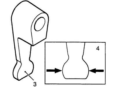
4. The permissible width of the leash is 15.90 - 15.95 mm.
Front housing and differential lock drive
1. Check the condition of the bearing seats in the crankcase. If necessary, restore the seats or replace the crankcase.
2. Check the locking lever shaft and housing holes for wear.
3. Measure the leash at its widest point.
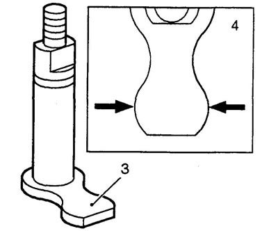
4. The permissible width of the leash is 15.90 - 15.95 mm.
5. Measure the groove width of the lock engagement rod. Permissible groove width 16.00 -16.01 mm.
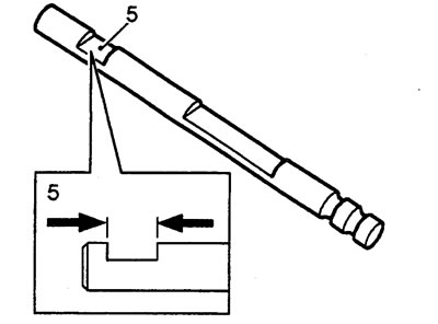
6. Check the condition of the grooves of the locking rod for installing the retainer.
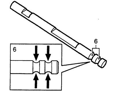
7. Check the condition of the retainer spring.
8. Check the condition of the retainer ball.
9. Check the condition of the lock engagement plug.
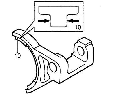
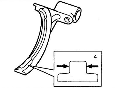
10. Measure the thickness of the locking fork fingers. The permissible thickness of fingers is 7.92 - 7.97 mm.
11. Check the condition of the spring and retaining rings of the locking fork.
12. Measure the free length of the spring. Minimum length 84.58 mm.
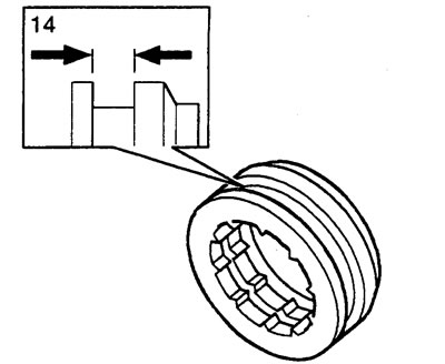
13. Check the condition of the ratchet ring teeth.
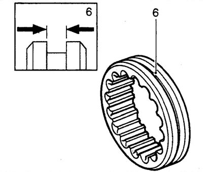
14. Measure the width of the ratchet ring grooves. Permissible groove width 8.05 - 8.20 mm.
15. Check the condition of the splines and threads of the output shaft.
16. Check the condition of the shaft teeth that engage with the ratchet ring.
Rear crankcase
1. Check the crankcase for cracks and other damage.
2. Check the condition of the speedometer drive gears.
3. Check the condition of the splines and threads of the output shaft.
Main crankcase
1. Check the condition of the bearing seats in the crankcase. If necessary, restore the seats or replace the crankcase.
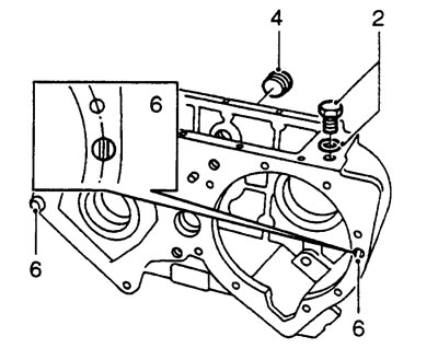
2. Unscrew the drain plug.
The article was copied from the website: www.lrman.ru
3. Replace the sealing washer and tighten the plug to 30 Nm.
4. Unscrew the level plug. Assess the condition of the plug and crankcase threads.
5. Tighten the cap by hand.
6. Check the presence of guide pins on the crankcase. Install the pin slots as shown in the figure.
7. Check the condition of the retainer ball.
8. Check the condition of the retainer spring.
- Secondary shaft drive gear housing 1. Check the condition of the bearing seats in the crankcase. If necessary, restore the seats or replace the crankcase.
- Shift fork and rod
Note: If you are not planning to replace the fork, there is no need to remove it from the stem. When replacing, apply Loctite 290 locking adhesive to the fork mounting screw threads.
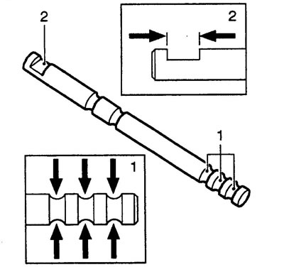
1. Check the condition of the grooves of the row shift rod for installing the locking pin.
2. Measure the width of the shift rod groove. Permissible groove width 16.00 - 16.01 mm.
3. Check the condition of the shift fork.
4. Measure the thickness of the lock engagement fork fingers. The permissible thickness of fingers is 7.37-7.47 mm.
Differential
1. Check for wear, chips or cracks on the teeth of the satellites and side gears.
2. Check the cross shafts and holes in the differential cups for wear.
Note: It is important that the satellites and shafts are installed in their original locations.
3. Check that the retaining ring is not deformed.
4. Check the condition of the splines and threads of the differential shafts.
5. Check the condition of the clutch splines and the gear shift hub.
6. Measure the groove width of the shift clutch. The permissible groove width is 7.5 - 7.6 mm.
7. Check for wear, chips or cracks on the teeth of the upper and lower row gears.
Comments on this article