Contents: Review ⇩ Clutch master cylinder ⇩ Release of the coaxial working…⇩ Coaxial slave cylinder ⇩ Clutch housing assembly ⇩ Clutch slave disc ⇩ Flywheel ⇩ Tightening torques ⇩
Review
The operation of the clutch system is based on the well-known principle of hydraulic actuation of a single driven plate and a diaphragm spring clutch housing assembly from the clutch pedal. When the clutch pedal is depressed, hydraulic fluid is pumped through the master cylinder, the piping system and the coaxial slave cylinder and, ultimately, drives the clutch fingers to disengage the clutch and disengage the drive and crankshaft. When the foot is removed from the pedal, the spring presses the pressure plate against the driven plate, which, in turn, is pressed against the flywheel. As a result, the engine crankshaft meshes with the transmission input shaft, forcing them to rotate at the same speed.
The clutch system has a conventional design and includes the following main components:
- Clutch master cylinder and pressure lines
- Coaxial slave cylinder assembly release and maximum torque limiter
- Damper for absorbing vibrations (for left-hand drive vehicles only)
- Coaxial slave cylinder
- Clutch housing assembly
- Clutch slave disc
- Flywheel
Clutch master cylinder
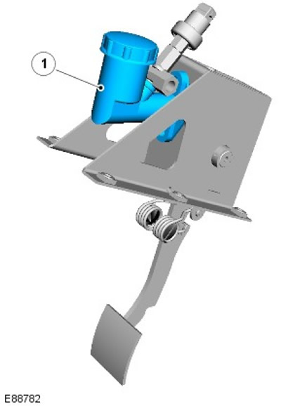
| Pos. | Spare part number | Name |
| 1 | - | Clutch master cylinder |
The clutch master cylinder is attached directly to the pedal box assembly located in the driver's side footwell.
The cylinder contains a piston assembly with a rod connected to the clutch pedal and spring. When pressed, the clutch pedal pushes the piston through a lever mechanism. Further pressing of the pedal increases the pressure in the cylinder and pipes.
The cylinder has two hydraulic connections:
- With low pressure feed pipe (through which fluid is supplied from the brake fluid reservoir)
- With high pressure tube
The pedal travel is limited by an upper stop built into the master cylinder and a lower stop built into the pedal mounting block.
Release of the coaxial working cylinder assembly
NOTE: Illustration shows right hand drive vehicle.
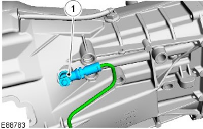
| Pos. | Spare part number | Name |
| 1 | - | Slave cylinder assembly release and maximum torque limiter |
The coaxial slave cylinder outlet assembly connects the external lines to the clutch release system integrated into the clutch housing. A mounting bracket ensures the correct orientation of the assembly. A seal is provided between the assembly and the clutch housing.
Original article on the web portal: LRMAN.ru
Inside the slave cylinder release unit is a maximum torque limiter. This element is designed to limit the flow of hydraulic fluid during the upward stroke of the clutch pedal. When the pedal is pressed normally, this limitation is not noticeable, but in the event of its unintentional release (for example, when a wet boot slips off the clutch pedal) peak torque limits the return flow rate and protects the transmission and drivetrain from excessive shock loads that can cause damage.
On left-hand drive vehicles, the hydraulic piping system contains an anti-vibration damper inserted into the peak torque limiter socket. This is necessary to reduce pedal noise or vibration during clutch operation.
Coaxial slave cylinder
The coaxial slave cylinder assembly consists of a clutch release bearing and a slave hydraulic cylinder. The entire unit is secured to the front of the gearbox with 3 bolts. The bolts are asymmetrically positioned, which ensures the required angular position of the slave cylinder, which is also centered by a flange. In its free state, the slave cylinder is fully extended, and after installation of the clutch housing on the engine, it automatically takes the correct position. The unit does not require any adjustment or regulation.
Clutch housing assembly
The clutch housing assembly includes a pressure plate, housing and diaphragm. It is mounted on the flywheel and rotates with it.
The surface of the pressure plate is machined to ensure tighter contact with the driven disk. Protrusions along the outer diameter of the pressure plate connect it to the casing using leaf springs. The leaf springs are equipped with sheets that help move the pressure plate away from the driving disk when the clutch pedal is pressed.
The housing contains all the components of the pressure plate. Flanged rivets support the diaphragm inside the cover. The rivet heads are chamfered to allow the diaphragm to rotate when pressure is applied to it from the release bearing. The holes in the housing are located on the pins on the flywheel, and additional holes provide fastening of the housing to the flywheel. Enlarged holes in the housing provide ventilation of the contact surfaces of the driven plate, pressure plate and flywheel.
The diaphragm comprises a cast ring with petals. The diaphragm is secured to the housing with flanged rivets. The inner head of each rivet is chamfered to allow the diaphragm to rotate when the clutch is engaged or disengaged. When force is applied to the diaphragm petals from the release bearing, the diaphragm pivots on the rivets and moves away from the pressure plate, relieving the pressure plate and allowing the driven plate to slide between the pressure plate and the flywheel.
Clutch slave disc
The clutch driven disc is located between the flywheel and the pressure plate of the clutch housing assembly. The clutch driven disc has a splined hub that meshes with the splines of the transmission input shaft. The splined hub is located on an inner plate containing three pre-damping compression springs. The inner plate is supported by springs capable of compressing in both directions to reduce engine vibration when idling. The inner plate is supported by four even larger compression springs, which in turn are located on a center plate. The hub is located between the center plate and a friction damper. The friction damper includes spring rings that are located between the hub and the center plate. The spring rings reduce transmission noise and vibration associated with cyclic excitation of the engine.
Flywheel
The single flywheel is bolted to a flange on the engine crankshaft. The flywheel is correctly positioned using a pin. The ring gear is located on the outside diameter of the flywheel and is located opposite the flange. The ring gear is fixed to the flywheel and is a serviceable element that can be replaced if damaged or worn.
In order to provide a smooth surface for engagement of the driven clutch disc, the working surface of the flywheel is machined.
Tightening torques
| Description | Nm | lb-ft |
| Clutch Pressure Plate Bolts (new bolts need to be installed) | 29 | 21 |
| Clutch slave cylinder mounting bolts | 10 | 7 |
| Clutch master cylinder to pedal assembly mounting bolts | 23 | 17 |
| Bolts securing the clutch pedal assembly to the engine compartment bulkhead | 23 | 17 |
| Clutch Master Cylinder Rod Nuts | 23 | 17 |
Comments on this article