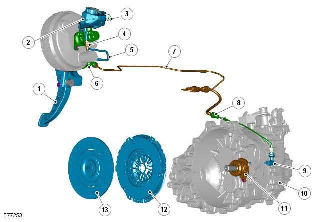
| Pos. | spare part no | Name |
| 1 | - | clutch pedal |
| 2 | - | Reservoir for hydraulic brake/clutch release |
| 3 | - | Liquid level sensor |
| 4 | - | Connector |
| 5 | - | Low pressure hose |
| 6 | - | master cylinder |
| 7 | - | high pressure clutch line |
| 8 | - | Connector |
| 9 | - | Clutch bleed adapter |
| 10 | - | Transmission |
| 11 | - | Slave cylinder and clutch release bearing |
| 12 | - | Clutch cover assy |
| 13 | - | driven disk |
The clutch has a traditional design with a single driven plate and a diaphragm spring clutch cover. The hydraulic drive is actuated by the clutch pedal.
The main elements of the clutch is the clutch cover assembly (pressure plate), engine flywheel and driven disc. The clutch housing, together with the flywheel and the driven disk, forms a friction system, it is bolted to the flywheel inside the housing.
Clutch cover
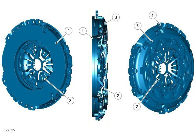
| Pos. | spare part no | Name |
| 1 | - | pressure plate |
| 2 | - | diaphragm spring |
| 3 | - | Lid |
| 4 | - | Mounting holes |
The clutch cover provides the transmission of engine torque through the driven disk to the input shaft. The contact force required to transmit the motor torque is provided by a slotted diaphragm spring. Due to the low actuation force, the diaphragm spring allows the driver to exert less force on the clutch pedal. The pressure plate has a friction surface with which the driven plate engages.
The diaphragm spring is a compressed type spring actuated by a working cylinder. During operation of the slave cylinder, the force from the diaphragm spring is transmitted through the clutch housing housing to the flywheel to which it is screwed. The pressure on the driven disk weakens and the transmission of motion to the gearbox is turned off.
The clutch cover pressure plate is attached to the clutch housing by leaf springs. The cams on the pressure plate protrude through holes in the crankcase, and the outer diaphragm springs rest on the cams. The pressure plate is attached to the body by means of bolts and wire rings. During the operation of the working cylinder, the pressure on the diaphragm springs weakens and the pressure plate can rotate on the cams, relieving pressure on the driven disc.
Driven disk
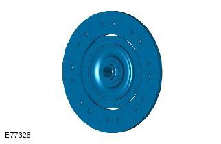
The driven disc is the central connecting element in the clutch. When combined with the clutch cover assembly, it separates and links the engine and transmission, connecting the engine crankshaft to the transmission input shaft.
The driven disk is a friction disk of a rigid type. To reduce noise and reduce wear on the gearbox, the dual flywheel absorbs torque fluctuations caused by combustion processes.
Double flywheel
The dual flywheel has two main elements: the primary section is attached to the crankshaft of the engine, and the clutch cover assembly is attached to the secondary section.
The starter ring gear is fixed on the outer perimeter of the primary section. The starter motor uses a ring gear to turn the engine's crankshaft when starting. The primary section is fixed to the crankshaft with 8 bolts. The pin on the crankshaft flange ensures the correct position of the flywheel.
The secondary section has a smooth friction surface to which the friction material of the driven disc is connected. The pins and dowel holes ensure proper alignment and fastening of the clutch cover assembly.
The primary and secondary sections are connected with long helical springs. The two sections can rotate in opposite directions, rotation is limited by coil springs that absorb torsional load when the clutch is engaged and torsional vibrations from the engine.
Comments on this article