Contents: Power flow in first gear ⇩ Power flow in second gear ⇩ Power flow in third gear ⇩ Power flow in fourth gear ⇩ Power flow in fifth gear ⇩ Power flow in sixth gear ⇩ Power flow in reverse gear ⇩ Differential ⇩ Reverse gear switch ⇩ 1st gear position switch ⇩
Power flow in first gear
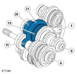
| Pos. | Spare part number | Name |
| A | - | Primary shaft |
| B | - | Intermediate shaft 1st - 2nd gear and 5th - 6th gear |
| 4 | - | Ring gear |
| 15 | - | 1st gear pinion |
| 19 | - | 1st - 2nd gear clutch |
| 20 | - | Main gear 1st - 2nd gear and 5th - 6th gear |
| 21 | - | 1st gear intermediate gear |
When 1st gear is selected, the 1st-2nd clutch is moved by the shift fork along the synchronizer hub to the 1st intermediate gear. The clutch and synchronizer hub lock the 1st intermediate gear on the 1st-2nd and 5th-6th intermediate shaft.
The engine torque is transmitted to the primary shaft via the clutch. The 1st gear pinion on the primary shaft transmits power to the 1st gear intermediate gear. From there, power is transmitted to the 1st-2nd and 5th-6th gear intermediate shaft and the final drive, which in turn transmits power to the crown gear. The crown gear is connected to the axle shafts via the differential.
Power flow in second gear
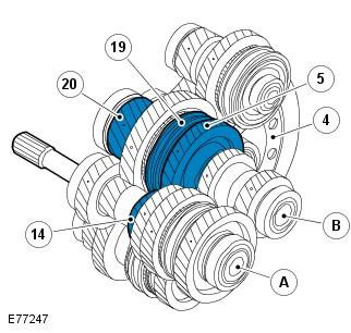
| Pos. | Spare part number | Name |
| A | - | Primary shaft |
| B | - | Intermediate shaft 1st - 2nd gear and 5th - 6th gear |
| 4 | - | Ring gear |
| 5 | - | 2nd gear intermediate gear |
| 14 | - | 2nd gear pinion |
| 19 | - | 1st - 2nd gear clutch |
| 20 | - | Main gear 1st - 2nd gear and 5th - 6th gear |
When 2nd gear is selected, the 1st-2nd clutch is moved by the shift fork along the synchronizer hub to the 2nd intermediate gear. The clutch and synchronizer hub lock the 2nd intermediate gear on the 1st-2nd and 5th-6th intermediate shaft.
The engine torque is transmitted to the primary shaft via the clutch. The 2nd gear pinion on the primary shaft transmits power to the 2nd gear intermediate gear. From there, power is transmitted to the 1st-2nd and 5th-6th gear intermediate shaft and the final drive, which in turn transmits power to the crown gear. The crown gear is connected to the axle shafts via the differential.
Power flow in third gear
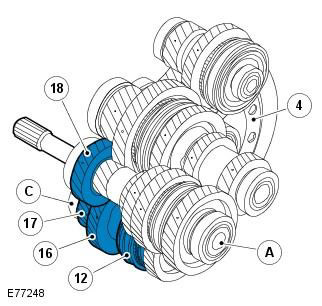
| Pos. | Spare part number | Name |
| A | - | Primary shaft |
| C | - | Intermediate shaft 3rd - 4th gear |
| 4 | - | Ring gear |
| 12 | - | 3rd - 4th gear clutch |
| 16 | - | 3rd gear intermediate gear |
| 17 | - | Main gear 3rd - 4th gear |
| 18 | - | 3rd gear pinion |
When 3rd gear is selected, the 3rd-4th clutch is moved by the shift fork along the synchronizer hub to the 3rd intermediate gear. The clutch and synchronizer hub lock the 3rd intermediate gear on the 3rd-4th intermediate shaft.
The engine torque is transmitted to the primary shaft via the clutch. The 3rd gear pinion on the primary shaft transmits power to the 3rd gear intermediate gear. From there, power is transmitted to the 3rd - 4th gear intermediate shaft and the final drive, which in turn transmits power to the crown gear. The crown gear is connected to the axle shafts via the differential.
Power flow in fourth gear
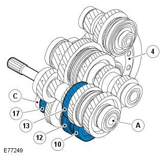
| Pos. | Spare part number | Name |
| A | - | Primary shaft |
| C | - | Intermediate shaft 3rd - 4th gear |
| 4 | - | Ring gear |
| 10 | - | 4th gear intermediate gear |
| 12 | - | 3rd - 4th gear clutch |
| 13 | - | 4th gear pinion |
| 17 | - | Main gear 3rd - 4th gear |
When 4th gear is selected, the 3rd-4th clutch is moved by the shift fork along the synchronizer hub to the 4th intermediate gear. The clutch and synchronizer hub lock the 4th intermediate gear on the 3rd-4th intermediate shaft.
The engine torque is transmitted to the primary shaft via the clutch. The 4th gear pinion on the primary shaft transmits power to the 4th gear intermediate gear. From there, power is transmitted to the 3rd - 4th gear intermediate shaft and the final drive, which in turn transmits power to the crown gear. The crown gear is connected to the axle shafts via the differential.
Power flow in fifth gear
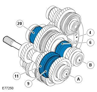
| Pos. | Spare part number | Name |
| A | - | Primary shaft |
| B | - | Intermediate shaft 1st - 2nd gear and 5th - 6th gear |
| 4 | - | Ring gear |
| 6 | - | 5th gear pinion |
| 9 | - | 5th - 6th gear clutch |
| 11 | - | 5th gear intermediate gear |
| 20 | - | Main gear 1st - 2nd gear and 5th - 6th gear |
When 5th gear is selected, the 5th-6th clutch is moved by the shift fork along the synchronizer hub to the 5th intermediate gear. The clutch and synchronizer hub lock the 5th intermediate gear on the input shaft.
The engine torque is transmitted to the primary shaft via the clutch. The 5th-6th gear clutch and the 5th gear intermediate gear, located on the primary shaft, transmit power to the 5th gear gear. From there, power is transmitted to the 1st-2nd and 5th-6th gear intermediate shaft and the final drive, which in turn transmits power to the crown gear. The crown gear is connected to the axle shafts via the differential.
Power flow in sixth gear
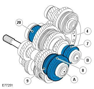
| Pos. | Spare part number | Name |
| A | - | Primary shaft |
| B | - | Intermediate shaft 1st - 2nd gear and 5th - 6th gear |
| 4 | - | Ring gear |
| 7 | - | 6th gear pinion |
| 8 | - | 6th gear intermediate gear |
| 9 | - | 5th - 6th gear clutch |
| 20 | - | Main gear 1st - 2nd gear and 5th - 6th gear |
When 6th gear is selected, the 5th-6th clutch is moved by the shift fork along the synchronizer hub to the 6th intermediate gear. The clutch and synchronizer hub lock the 6th intermediate gear on the input shaft.
The engine torque is transmitted to the primary shaft via the clutch. The 5th-6th gear clutch and the 6th gear intermediate gear, located on the primary shaft, transmit power to the 6th gear gear. From there, power is transmitted to the 1st-2nd and 5th-6th gear intermediate shaft and the final drive, which in turn transmits power to the crown gear. The crown gear is connected to the axle shafts via a differential.
Power flow in reverse gear
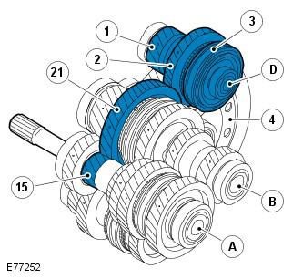
| Pos. | Spare part number | Name |
| A | - | Primary shaft |
| B | - | Intermediate shaft 1st - 2nd gear and 5th - 6th gear |
| D | - | Reverse gear shaft |
| 1 | - | Main gear for reverse gear |
| 2 | - | Reverse intermediate gear |
| 3 | - | Reverse gear clutch |
| 4 | - | Ring gear |
| 15 | - | 1st gear pinion |
| 21 | - | 1st gear intermediate gear |
When reverse gear is selected, the reverse clutch is moved by the shift fork along the synchronizer hub to the reverse intermediate gear.
The synchronizer clutch and hub lock the reverse intermediate gear on the reverse gear shaft.
The engine torque is transmitted to the primary shaft via the clutch. The 1st gear pinion on the primary shaft transmits power to the 1st gear intermediate gear. The power is then transmitted to the reverse gear intermediate gear and then to the reverse gear clutch. From there, the power is transmitted to the 1st-2nd and 5th-6th gear intermediate shaft and the final drive, which in turn transmits power to the ring gear. The ring gear is connected to the axle shafts via a differential.
Differential
The differential distributes torque transmitted from the gearbox equally between the left and right front axle shafts, and also transmits torque to the rear differential via the transfer case.
The differential is located at the rear of the gearbox housing. Both sides of the differential are connected to the left and right half shafts, which transmit torque to the front wheels. Through a splined shaft on the right side of the gearbox, the differential is also connected to the transfer case, which transmits torque to the rear wheels.
Reverse gear switch
The reverse gear switch is located at the front of the transmission case, above the 1st gear position switch. This switch is used by the anti-lock brake system (ABS) module to control the hill descent control (HDC) system and the operation of the reversing lights.
1st gear position switch
The 1st gear switch is located at the front of the transmission housing, below the reverse gear switch. The ABS module uses this switch to control the HDC system.
Comments on this article