car logo Ford
car logo Volkswagen
car logo BMW
car logo Opel
car logo Audi
car logo Toyota
car logo Peugeot
English Русский
Български
Беларускі
Український
Српски
Hrvatski
Română
Polski
Slovenský
Magyar


Main
Freelander
Discovery
Range Rover
Defender
Contacts
Articles

Mechanical gearbox device (Freelander 2)

 
  • Main
  • Freelander
  • Freelander 2
  • Power unit
  • Mechanical transmission
  • Mechanical gearbox device
 
        0  
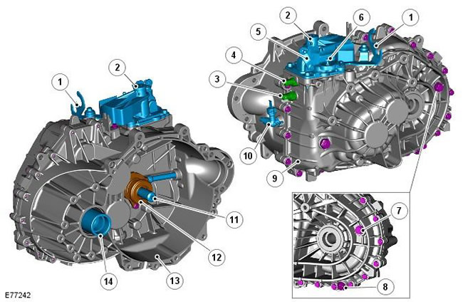
Contents: Neutral gear sensor ⇩ Switching mechanism ⇩ Gear selector shafts ⇩
The shift cable and selector lever are described in the section on external controls. For more information, refer to the chapter: External Controls (308-06 Manual Transaxle/Transaxle External Controls, Description and Operation).

The shift cable and selector lever are described in the section on external controls. For more…


Pos.Spare part numberName
1-Cable mounting bracket
2-Trailing arm
3-1st gear position switch
4-Reverse gear switch
5-Wishbone
6-Shift cable ball head
7-Transmission Fluid Level Plug/Filler Plug
8-Gearbox drain plug
9-Gearbox housing
10-Clutch Hydraulic Air Bleed Adapter
11-Primary shaft
12-Clutch slave cylinder
13-Clutch housing
14-Differential output (right side shown).


Neutral gear sensor


(vehicles with Stop/Start system - from 2010 model year)
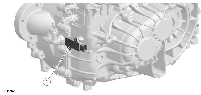
(vehicles with Stop/Start system - from 2010 model year)


Pos.Spare part numberName
1-Neutral gear sensor


The magnetic inductive PLCD sensor, installed on vehicles with the Stop/Start system, is located outside the gearbox housing and is hardwired to the engine control unit. The sensor is designed to detect when the neutral gear is engaged within a calibrated window. For more information, refer to the chapter: Starting System (303-06C Starting System - 2.2L Duratorq - Td4, Vehicles manufactured from 03/2009 onwards, Description and Function).

Switching mechanism
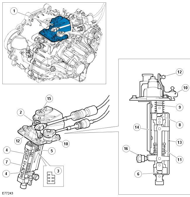

Switching mechanism


Pos.Spare part numberName
1-Switching mechanism
2-Ball limiter 5th - 6th gear
3-Gear shift linkage
4-Flange
5-Gear shift lever finger
6-Lower gear selector
7-Selector rod
8-Upper gear selector
9-Spring
10-Trailing arm
11-Spring
12-Wishbone
13-Fixing plate
14-Carrier plate
15-Air release cap
16-Selector ball stop

The transmission is controlled by two shift cables connected to the selector lever. The movement of the selector lever is transmitted via the cables to two lever assemblies on the top of the transmission. The levers operate the gearshift mechanism to select the desired gear ratio.

The shift mechanism is located at the front of the gearbox and transmits the movement of the shift cable to the shift actuators.


The shift mechanism is a single unit secured to the gearbox housing with four bolts. The shift mechanism moves the upper and lower gear selector forks via transverse and longitudinal levers at the top of the shift mechanism. There are two upper gear selector forks and two lower gear selector forks:
  • The two upper gear shift forks are used to engage reverse, 1st and 2nd gears.
  • The two lower gear shift forks are used to engage 3rd, 4th, 5th and 6th gears.

Four shift forks transmit the movement from the shift mechanism to the corresponding synchronizer clutch. The shift forks are mounted in bearings in the gearbox housing.

Two carrier plates transmit torque from the longitudinal lever to the sliding shift selectors. The carrier plates are located and operate in a groove on the selector plate.

The carrier plates can move in the vertical plane between 4 positions. The different gears are selected from one of the four positions as follows:
  • The top position - the gear selector selects reverse gear
  • Second top position - the gear selector selects 1st and 2nd gears
  • Second lower position - the gear selector selects 5th and 6th gears
  • The lowest position - the gear selector selects 3rd and 4th gears

The gear shift mechanism has two springs that return the selector lever to the neutral position.

Gear selector shafts
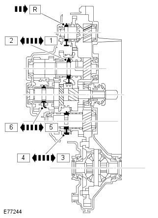

Gear selector shafts


(Information obtained from the website www.LRman.ru)


The illustration above shows the clutches for each gear group. When these clutches are moved according to the selection of the shift mechanism, the required gears are connected to obtain the required output ratio.

The clutch is part of the synchronizer assembly, which also includes a flange and a hub. Each synchronizer hub is connected to its shaft by means of splines and rotates together with the shaft. Intermediate gears are installed on both sides of each synchronizer hub. The intermediate gears rotate freely on the shaft (except for the reverse gear). Each intermediate gear is in constant engagement with its drive gear. The synchronizer is located between the synchronizer hub and the intermediate gear.

The synchronizers are located on the shafts in the gearbox as follows:
  • The synchronizer 1st - 2nd gear is located on the intermediate shaft 1st - 2nd, 5th - 6th gear
  • The 3rd - 4th gear synchronizer is located on the 3rd - 4th gear intermediate shaft
  • The synchronizer of 5th - 6th gears is located on the primary shaft
  • The reverse gear synchronizer is located on the reverse gear shaft

Synchronizer rings expand when heated, as do the elements they are in contact with. As a result, no safety margin is required to counteract expansion. Single and double synchronization intermediate gears do not have cones. This function is performed by the inner synchronizer ring.


This article is available at russian, bulgarian, belarusian, ukrainian, serbian, croatian, romanian, polish, slovak, hungarian
Article review: Roman Mitrofanov


Previous articles
Manual transmission specification
Overview and location of the manual transmission

Current article
Mechanical gearbox device

Next articles
Gearbox gear block
Power flow in different gears
Description and principle of operation of the clutch
Inspection and verification
Table of signs of malfunction
Bleeding the Clutch System
Adjusting the gear shift cable
Clutch specification


Similar articles from Land Rover repair manuals:
• Front disc brake device Discovery 3 (2004-2009)
• Rear gearbox seal Range Rover 3 (2001-2012)
• Description and operating principle of a manual gearbox Defender 2007+ (2007-2016)

Comments on this article


No comments yet


How much will 20 + 22 =


Freelander 2 
  • General information
  • Using the manual
  • Repair technique
  • Precautionary measures
  • Road test
  • Fault codes
  • Identification codes
  • Jacking and lifting
  • Maintenance - Diesel
  • Maintenance - petrol
  • Chassis
  • Suspension
  • Front suspension
  • Rear suspension
  • Wheels and tires
  • Terrain response
  • Transmission system
  • Cardan shaft
  • Rear drive axle
  • Rear axle shafts
  • Front axle shafts
  • Brake system
  • Parking brake
  • Hydraulic brake
  • Brake booster
  • Anti-lock braking system
  • Exchange rate stability
  • Steering
  • Steering column
  • Power unit
  • Engine device
  • Engine repair
  • Description of the cooling system
  • Cooling system repair
  • Fuel supply
  • Drive units
  • Launch system
  • Ignition system
  • Exhaust toxicity
  • Air filtration
  • Fuel vapor control
  • Electronic control part
  • Automatic gearbox
  • Gearbox cooling
  • Automatic transmission controls
  • Mechanical transmission
  • Transfer case
  • Exhaust system
  • Fuel tank and lines
  • Speed control
  • Electrical equipment
  • Climate control system
  • Climate control
  • Additional climate control
  • Instrument panel
  • Sound signal
  • Information and messages
  • Assistance with parking
  • Battery and alternator
  • Information and entertainment
  • Outdoor Lighting
  • Interior lighting
  • Communication network
  • Wiring harnesses
  • Anti-theft system
  • Multifunctional modules
  • Body and coating
  • Body front panels
  • Lockable body parts
  • Interior trim
  • Rear view mirrors
  • Car seats
  • Glass, frames and mechanisms
  • Instrument panel and console
  • Handles, locks, latches
  • Windshield wipers and washers
  • Sunroof
  • Bumpers
  • Seat belt system
  • Restraint system
  • Body repairs
  • Front end repairs
  • Roof element repairs
  • Side panel repairs
  • Tailgate repairs
  • Subframe and mounts

Freelander 1 
  • General information
  • Using the manual
  • Precautionary measures
  • Technique
  • Specifications
  • Connection tightening torques
  • Maintenance
  • Power unit
  • Diesel engine Td4
  • Petrol engine K1.8
  • Piston group K1.8
  • KV6 petrol engine
  • Piston group KV6
  • Decreased toxicity
  • Motor control EDC
  • Engine management MEMS
  • Motor control Siemens
  • Fuel supply diesel Td4
  • Fuel supply for K1.8 engine
  • Fuel supply of KV6 engine
  • Cooling diesel Td4
  • Engine cooling K1.8
  • Engine cooling KV6
  • Exhaust system Td4
  • Exhaust system K1.8
  • Exhaust system KV6
  • Clutch
  • Mechanical transmission
  • Transfer case
  • Automatic gearbox
  • Chassis
  • Drive shafts
  • Rear axle and final drive
  • Steering
  • Front suspension
  • Rear suspension
  • Brake system
  • Body and coating
  • Passive safety
  • Doors, locks and glass
  • Exterior body parts
  • Interior trim details
  • Seats
  • Roof hatch
  • Roof
  • Body geometry
  • Body parts repair
  • Sealing and corrosion
  • Electrical equipment
  • Heating and ventilation
  • Air conditioning
  • Windshield wipers and washers
  • Starting engine and charging
  • Lighting and headlights
  • Control modules
  • Safety system
  • Window management
  • Entertainment systems
  • Wiring harnesses
  • Governing bodies
  • Devices


LRman.ru © 2013-2026 | Mobile version | Free Lander | Discovery | Range Rover | Defender | Contacts | | Sitemap |
Car repair and service instructions Land Rover: Freelander, Discovery, Range Rover, Defender
We use cookies to make pages load faster and provide a more user-friendly experience 🍪