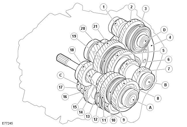
| Pos. | Spare part number | Name |
| A | - | Primary shaft |
| B | - | Intermediate shaft 1st - 2nd gear, 5th - 6th gear |
| C | - | Intermediate shaft 3rd - 4th gear |
| D | - | Reverse gear shaft |
| 1 | - | Main gear of reverse gear |
| 2 | - | Reverse intermediate gear |
| 3 | - | Reverse gear clutch |
| 4 | - | Main gear of differential |
| 5 | - | 2nd gear intermediate gear |
| 6 | - | 5th gear pinion |
| 7 | - | 6th gear pinion |
| 8 | - | 6th gear intermediate gear |
| 9 | - | 5th - 6th gear clutch |
| 10 | - | 4th gear intermediate gear |
| 11 | - | 5th gear intermediate gear |
| 12 | - | 3rd - 4th gear clutch |
| 13 | - | 4th gear pinion |
| 14 | - | Fixed 2nd gear pinion |
| 15 | - | Fixed 1st gear pinion |
| 16 | - | 3rd gear intermediate gear |
| 17 | - | Leading gear 3rd - 4th gear |
| 18 | - | 3rd gear pinion |
| 19 | - | 1st - 2nd gear clutch |
| 20 | - | Drive gear 1st - 2nd and 5th - 6th gears |
| 21 | - | 1st gear intermediate gear |
The gears are arranged on four shafts as follows:
- Primary shaft
- Intermediate shaft 1-2, 5-6
- Intermediate shaft 3-4
- Reverse gear shaft
In order to keep the shafts short, the engagement rings are welded directly to the intermediate gear and needle bearings with inner rings are used instead of retaining rings. The inner rings sit on the shaft inside the intermediate gears and extend longitudinally beyond each intermediate gear. When the elements on the shaft are pulled together, the inner rings are held so that the intermediate gears maintain the clearance they need to rotate. The input shaft elements are pulled together by a bolt located at the end of the shaft. The 3rd - 4th gear intermediate shaft elements are held together by a press joint and a bolt located at the end of the shaft. The 1st - 2nd, 5th - 6th gear intermediate shaft elements are held together by a press joint on the 5th and 6th gear pinion.
Comments on this article