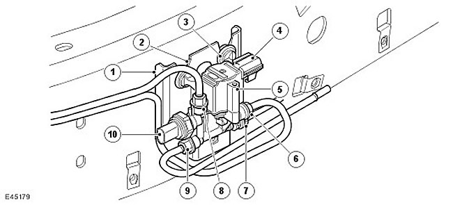
| Item name | Spare part catalog number | Description |
| 1 | - | Chassis mounting bracket |
| 2 | - | Mounting groove |
| 3 | - | Rubber vibration-isolating mounts (3 pcs.) |
| 4 | - | Electrical connector |
| 5 | - | Receiver valve block, valves and solenoids in assembly |
| 6 | - | Receiver nipple |
| 7 | - | Rear valve block nipple |
| 8 | - | Front valve block nipple |
| 9 | - | Compressor block nipple |
| 10 | - | Pressure sensor |
The receiver valve block regulates the accumulation of air in the receiver and its flow from the receiver. The receiver valve block also contains a pressure sensor in the system.
The receiver valve block is secured to a bracket on the outside of the left longitudinal beam of the chassis, between the receiver and the compressor unit. The valve block is located in the noise-proof casing of the compressor unit, protecting it from dirt and damage by stones. The valve block has three mounting brackets with rubber vibration-insulating supports, which are installed in the chassis bracket with three grooves. The vibration-insulating rubber supports are located in V-shaped slots and are pulled down to their seat in the slots.
The valve block has four connecting pneumatic pipes with Voss-type nipples. The nipples provide air supply from the compressor block, to the receiver and from the receiver, as well as to and from the front and rear valve blocks. The nipples for the compressor block and the front and rear valve blocks are connected by a common gallery in the valve block, ensuring the same pressure in them.
The valve block contains a solenoid valve, the operation of which is controlled by the air suspension control unit. The solenoid valve regulates the flow of pressure into and out of the receiver. The solenoid has a resistance of 2 ohms at 20°C (68°F). When current flows through it, the valve spool moves, allowing air to flow into and out of the receiver.
The valve block also contains a pressure sensor, which can be used to measure the air pressure in the elastic pneumatic elements and the receiver. The pressure sensor is connected to the air suspension control unit via an electrical connector. The control unit supplies the pressure sensor with a reference voltage of 5 V and monitors the signal voltage from the sensor.
Data taken from the website [www.LRman.ru]
Using this sensor, the control unit regulates the operation of the compressor unit and limits the nominal working pressure in the system to 244 psi (16.8 bar).
Comments on this article