| Item name | Spare part number | Description |
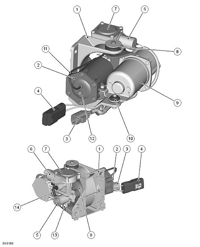
| 1 | - | support bracket |
| 2 | - | Air Dryer |
| 3 | - | Control outlet valve solenoid harness connector and temperature sensors. |
| 4 | - | Motor Harness Connector |
| 5 | - | Inlet |
| 6 | - | Control outlet valve |
| 7 | - | Exhaust valve |
| 8 | - | Rubber anti-vibration mount (2 pcs.) |
| 9 | - | electric motor |
| 10 | - | Rubber anti-vibration mount (1 PC.) |
| 11 | - | Control air tube |
| 12 | - | Supplying high pressure to the air suspension system |
| 13 | - | Compressor head temperature sensor |
| 14 | - | Compressor |
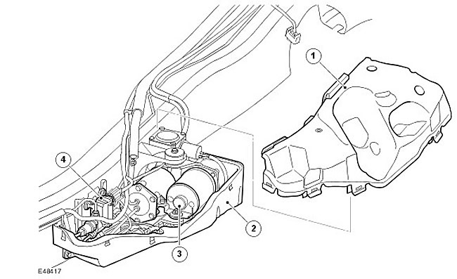
The compressor block is mounted on the outer side of the left longitudinal chassis beam, in front of the upper control lever. The block is attached to the longitudinal beam of the chassis with three bolts and is closed with a soundproof casing.
Noise cover
| Item name | Spare part number | Description |
| 1 | - | Top cover |
| 2 | - | bottom cover |
| 3 | - | Compressor block |
| 4 | - | Receiver valve block |
The soundproof casing consists of two parts, upper and lower, inside of which there is a compressor unit. The noise enclosure is a plastic box lined with soundproofing foam to reduce the noise produced by the compressor unit. The valve block of the receiver is also located in a soundproof casing, in front of the compressor block.
The main components and parts of the compressor unit:
- Piston compressor
- 12 V electric motor
- Control solenoid valve
- Exhaust valve
- Air Dryer
In the event of failure, the compressor unit is repairable, but only the following components are repairable: air dryer, control exhaust pipe and rubber mounts.
The compressor block is mounted on a bracket that is bolted to the chassis. The unit is attached to the bracket with flexible rubber anti-vibration mounts that prevent transmission of chassis noise generated by the operation of the compressor unit.
It is not necessary to depressurize the entire air suspension system to remove the compressor block. Front and rear valve blocks and receiver valve block in normal position (not energized) are closed, which does not allow pressure to escape from the pneumatic elastic elements and the receiver when the unit is disconnected.
There are conditions in which the operation of the compressor unit is prohibited. It is important not to confuse these system inhibitions with malfunctions. A complete list of prohibitions for the compressor block is given in the section "Air suspension control unit" of this chapter.
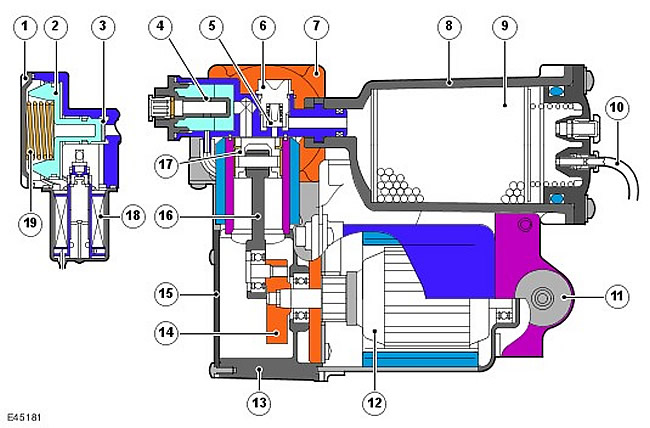
Compressor Block - Sectional View
| Item name | Spare part number | Description |
| 1 | - | exhaust valve cover |
| 2 | - | Plunger |
| 3 | - | Valve seat |
| 4 | - | Silencer inlet |
| 5 | - | Discharge valve |
| 6 | - | valve guide |
| 7 | - | Cylinder head |
| 8 | - | Dryer housing |
| 9 | - | Desiccant |
| 10 | - | Control outlet line |
| 11 | - | Rubber anti-vibration mount |
| 12 | - | Complete motor |
| 13 | - | Carter |
| 14 | - | Crank |
| 15 | - | crankcase cover |
| 16 | - | connecting rod |
| 17 | - | Piston |
| 18 | - | Control outlet valve |
| 19 | - | Spring - safety valve |
Control outlet valve
The control solenoid outlet valve is connected to the pneumatic gallery after the air dryer. When the control valve is open, it controls the main compressor outlet valve. This allows, if necessary, to release air from the elastic pneumatic elements.
When the solenoid is energized, the air control charge moves the exhaust valve plunger, allowing pressurized air to pass from the air bags and/or reservoir through the reservoir pilot valve into the compressor unit.
The electromagnet has a resistance of 4 ohms at 20°C (68°F).
Exhaust valve
The exhaust valve has three functions. It works in conjunction with the control bleed valve to bleed air from the air springs and/or reservoir as discussed above.
The valve also protects the system from excessive pressure. The valve is connected to the main pneumatic gallery, which is always under pressure from the pneumatic elastic elements or the receiver. The valve has a spring that limits the maximum working pressure to 370 lbf/in2 (23.0-25.5 bar).
The minimum pressure in the system is also controlled by the bleed valve so that even when the air is released, the pneumatic springs are maintained at an overpressure of 21 bar. This protects the pneumatic elastic element, ensuring that it moves relative to the piston without deformation.
Electric motor
The 12V DC motor has a rated operating voltage of 13.5V. The motor drives a crank that has an eccentric spike to which the compressor connecting rod is attached.
The electric motor has a temperature sensor mounted on the printed brush assembly. The sensor is connected to the air suspension control unit, which monitors the temperature and can stop the electric motor in case of overheating.
Compressor
The compressor contains a connecting rod driven by an electric motor with a piston that moves in a cylinder with a cylinder head. The electric motor turns a crank which moves the piston up and down in the cylinder. When the piston moves up, the air in the cylinder is compressed and fed through the pressure valve and the dryer into the system.
Dehumidifier
The dryer is part of the compressor unit. The dehumidifier contains a desiccant that controls the humidity of the air. Before compressed air is supplied to the receiver and/or system, it passes through a dryer, which removes moisture from the air.
When air is released from the system, it also passes through the dryer, and, taking moisture from the desiccant, is released into the atmosphere.
The dehumidifier is an important component of the system, ensuring the dryness of the air in the system. If there is moist air in the system, moisture can freeze and cause inefficient operation of the system or failure / failure of components and parts.
Comments on this article