car logo Ford
car logo Volkswagen
car logo BMW
car logo Opel
car logo Audi
car logo Toyota
car logo Peugeot
English Русский
Български
Беларускі
Український
Српски
Hrvatski
Română
Polski
Slovenský
Magyar


Main
Freelander
Discovery
Range Rover
Defender
Contacts
Articles

Description of the steering gear valve block (Freelander 2)

 
  • Main
  • Freelander
  • Freelander 2
  • Chassis
  • Steering
  • Description of the steering gear valve block
 
        0  
NOTE: Typical valve block shown
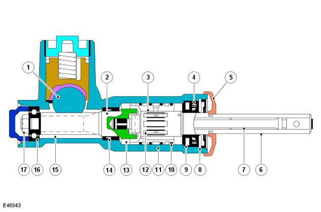

NOTE: Typical valve block shown


Pos.Spare part numberName
1-Rail
2-Gear shaft
3-Outer bushing
4-Oil bushing
5-Mud seal
6-Input shaft
7-Torsion
8-Retaining ring
9-Oil seal
10-Fluoroplastic ring (PTFE)
11-Steering gear housing
12-Grooves
13-Pinion - gear shaft to outer sleeve
14-Oil seal
15-Gear shaft teeth
16-Bearing
17-Pinion shaft nut

The valve block is an integral part of the steering gear. The main function of the valve block is to optimize the force on the steering wheel (for example, when parking) due to the operation of the hydraulic booster. The steering gear housing is an integral part of the steering gear assembly.

The steering gear housing has four ports for connecting the pressure line from the power steering pump, the return line to the reservoir, and the pressure lines to each side of the piston. A non-return valve and seal are installed in the port for the pressure line coming from the power steering pump. The valve block consists of an outer sleeve, an input shaft, a torsion bar, and a pinion shaft.

The valve block is located on the same axis as the pinion shaft, which is connected to the steering column via the input shaft. The valve block elements are located in the steering gear housing with a sealed cover. The outer sleeve is located in the main opening of the gear housing. Three annular grooves are made along its outer diameter. Fluoroplastic rings are installed between the grooves, which seal the opening of the gear housing. In each annular groove, radial holes are drilled through the wall of the sleeve. The axial opening of the outer sleeve is bored to the size of the input shaft. In the opening of the sleeve, six slots are machined at an equal distance from each other.


The ends of the slots are closed and do not protrude outward. Radial holes in the outer sleeve are drilled into each slot. The input shaft has two machined planes on its outer end, which provide for the connection of the fork of the intermediate shaft of the steering column. The planes ensure that the intermediate shaft is installed in the correct position to maintain the optimum phase angle. The inner end of the input shaft has a projection that mates with a slot in the pinion shaft. The position of the projection in the slot allows for a slight relative rotation of the input shaft and the pinion shaft before the projection touches the wall of the slot. This makes it possible, in the event of a failure of the hydraulic booster, to use the steering manually, thereby avoiding excessive loads on the torsion bar.

Along the circumference of the central part of the input shaft, longitudinal grooves are machined at equal distances from each other. The grooves are located alternately around the input shaft. The torsion bar is attached to the inner part of the input shaft and to the pinion shaft. The torsion bar is connected to the input shaft by means of a drive pin. In the central part, the torsion bar has a smaller diameter than at the ends. The smaller diameter allows the torsion bar to twist under the influence of the torque applied to the steering wheel, depending on the adhesion of the tires to the road surface. The pinion shaft has a projection in the center, which is connected with a projection on the steering rack. The projection on the input shaft enters the groove machined in the upper part of the pinion shaft. The pinion shaft is located in the gear housing and rotates on ball bearings.

(Information obtained from the website: «LRMAN.RU»)


This article is available at russian, bulgarian, belarusian, ukrainian, serbian, croatian, romanian, polish, slovak, hungarian
Article review: Roman Mitrofanov


Previous articles
Steering Specification
Inspection and verification
Table of signs of malfunction
Bleeding the Power Steering System
Power steering system flush
Power Steering Specification
Description of power steering
Description of the steering mechanism

Current article
Description of the steering gear valve block

Next articles
Description of the power steering pump
Description of the power steering fluid reservoir
Cooler for working fluid (i6 only)
The principle of operation of the power steering
Checking the pressure in the power steering circuit 2.2L Duratorq — TD4
Power Steering Pump 2.2L Duratorq — Td4
Removal and installation the steering gear
Power steering fluid cooler


Similar articles from Land Rover repair manuals:
• Receiver valve block Discovery 3 (2004-2009)
• Determining the central position of the steering gear Discovery 1 (1989-1998)
• Automatic transmission valve block Range Rover 3 (2001-2012)
• Steering gear centering Defender 2007+ (2007-2016)

Comments on this article


No comments yet


How much will 19 + 38 =


Freelander 2 
  • General information
  • Using the manual
  • Repair technique
  • Precautionary measures
  • Road test
  • Fault codes
  • Identification codes
  • Jacking and lifting
  • Maintenance - Diesel
  • Maintenance - petrol
  • Chassis
  • Suspension
  • Front suspension
  • Rear suspension
  • Wheels and tires
  • Terrain response
  • Transmission system
  • Cardan shaft
  • Rear drive axle
  • Rear axle shafts
  • Front axle shafts
  • Brake system
  • Parking brake
  • Hydraulic brake
  • Brake booster
  • Anti-lock braking system
  • Exchange rate stability
  • Steering
  • Steering column
  • Power unit
  • Engine device
  • Engine repair
  • Description of the cooling system
  • Cooling system repair
  • Fuel supply
  • Drive units
  • Launch system
  • Ignition system
  • Exhaust toxicity
  • Air filtration
  • Fuel vapor control
  • Electronic control part
  • Automatic gearbox
  • Gearbox cooling
  • Automatic transmission controls
  • Mechanical transmission
  • Transfer case
  • Exhaust system
  • Fuel tank and lines
  • Speed control
  • Electrical equipment
  • Climate control system
  • Climate control
  • Additional climate control
  • Instrument panel
  • Sound signal
  • Information and messages
  • Assistance with parking
  • Battery and alternator
  • Information and entertainment
  • Outdoor Lighting
  • Interior lighting
  • Communication network
  • Wiring harnesses
  • Anti-theft system
  • Multifunctional modules
  • Body and coating
  • Body front panels
  • Lockable body parts
  • Interior trim
  • Rear view mirrors
  • Car seats
  • Glass, frames and mechanisms
  • Instrument panel and console
  • Handles, locks, latches
  • Windshield wipers and washers
  • Sunroof
  • Bumpers
  • Seat belt system
  • Restraint system
  • Body repairs
  • Front end repairs
  • Roof element repairs
  • Side panel repairs
  • Tailgate repairs
  • Subframe and mounts

Freelander 1 
  • General information
  • Using the manual
  • Precautionary measures
  • Technique
  • Specifications
  • Connection tightening torques
  • Maintenance
  • Power unit
  • Diesel engine Td4
  • Petrol engine K1.8
  • Piston group K1.8
  • KV6 petrol engine
  • Piston group KV6
  • Decreased toxicity
  • Motor control EDC
  • Engine management MEMS
  • Motor control Siemens
  • Fuel supply diesel Td4
  • Fuel supply for K1.8 engine
  • Fuel supply of KV6 engine
  • Cooling diesel Td4
  • Engine cooling K1.8
  • Engine cooling KV6
  • Exhaust system Td4
  • Exhaust system K1.8
  • Exhaust system KV6
  • Clutch
  • Mechanical transmission
  • Transfer case
  • Automatic gearbox
  • Chassis
  • Drive shafts
  • Rear axle and final drive
  • Steering
  • Front suspension
  • Rear suspension
  • Brake system
  • Body and coating
  • Passive safety
  • Doors, locks and glass
  • Exterior body parts
  • Interior trim details
  • Seats
  • Roof hatch
  • Roof
  • Body geometry
  • Body parts repair
  • Sealing and corrosion
  • Electrical equipment
  • Heating and ventilation
  • Air conditioning
  • Windshield wipers and washers
  • Starting engine and charging
  • Lighting and headlights
  • Control modules
  • Safety system
  • Window management
  • Entertainment systems
  • Wiring harnesses
  • Governing bodies
  • Devices


LRman.ru © 2013-2026 | Mobile version | Free Lander | Discovery | Range Rover | Defender | Contacts | | Sitemap |
Car repair and service instructions Land Rover: Freelander, Discovery, Range Rover, Defender
We use cookies to make pages load faster and provide a more user-friendly experience 🍪