Power Steering Pump - TD4
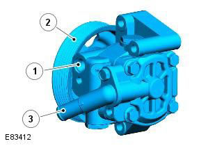
| Pos. | Spare part number | Name |
| 1 | - | Pressure outlet (to steering gear valve block) |
| 2 | - | Pulley |
| 3 | - | Suction hole (from the tank) |
A variable displacement vane pump supplies the required hydraulic pressure to the steering valve block. The pump is located at the front of the engine and is driven by a poly V-belt of the front auxiliary drive, which is driven directly from the crankshaft. The pump feed increases proportionally to the load applied to the steering valve block. A self-adjusting tensioner is used to maintain the required belt tension.
The pump includes 11 blades and a rotor. They are mounted on the input shaft and surrounded by a stator ring of variable volume. The blades rotate inside the stator ring and are driven by the shaft. As the blades rotate, the space between the blades increases due to the stator ring. This causes a vacuum between the blades, due to which liquid from the tank is drawn into this space through the suction hose. As the shaft rotates, the inlet opening of the blades, between which liquid is already located, closes, thus "locking" the liquid between the blades. Due to the stator ring, the space between the blades decreases, which leads to compression of the liquid located between the blades. As the shaft rotates further, the blades turn towards the outlet opening. As the blades pass the opening, liquid flows under pressure from the pump outlet through the discharge hose into the steering gear.
The stator ring moves inside the valve body. By moving the stator ring, the eccentricity of the shaft and blades relative to the stator ring can be changed. By decreasing the eccentricity, the volume of hydraulic fluid between the blades decreases, thereby maintaining a constant fluid supply. This reduces the power and torque required to turn the pump, thus improving efficiency. The pump has an internal control valve that controls the eccentricity of the stator ring and thereby changes the fluid flow rate according to needs.
At low engine speeds, the internal volume of the variable displacement pump reaches its maximum value to create a controlled fluid flow. As the engine speed increases, the pump speed increases. The increased flow inside the pump creates a back pressure in the pump. This back pressure causes the internal control valve to move the stator ring and reduce the internal volume of the pump to maintain a constant pump flow.
A regulating pressure reducing valve inside the pump limits the maximum pressure supplied to the steering gear to 115 bar (1667 psi) ±4 bar (58 psi) and also limits the maximum flow to 8.8 l/min (1.93 gpm) ±0.5 l/min (0.1 gpm) at 10 bar (145 psi). The pump displacement is 9.6 cc/rev (0.58 in³/rev).
Power Steering Pump - i6
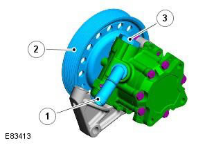
| Pos. | Spare part number | Name |
| 1 | - | Suction hole (from the tank) |
| 2 | - | Pulley |
| 3 | - | Pressure outlet (to steering gear valve block) |
A fixed-volume vane pump supplies hydraulic pressure to the steering gear valve block. The pump is located at the rear of the engine and is driven by a rear auxiliary drive poly V-belt, which is driven indirectly by the camshafts. The pump has a constant flow rate, independent of pump/engine speed. A self-adjusting tensioner is used to maintain the required belt tension.
The pump has a number of blades that rotate inside a stator ring and are driven by an input shaft. As the blades rotate, the stator ring causes the space between the blades to increase. This causes a vacuum between the blades, causing fluid to be drawn into this space from the tank through the suction hose. As the shaft rotates, the inlet opening of the blades, between which the fluid is already located, closes, thus "locking" the fluid between the blades. The stator ring causes the space between the blades to decrease, causing the fluid between the blades to be compressed. As the shaft rotates further, the blades turn toward the outlet opening. As the blades pass the opening, the fluid flows under pressure from the pump outlet opening through the discharge hose into the steering gear.
The supply of pressurized fluid is regulated by a pressure reducing valve with a flow regulator of the working fluid. The flow regulator ensures a constant supply of working fluid to the steering mechanism, regardless of the engine speed. The pressure reducing valve limits the maximum pressure at the pump outlet. The pump outlet has a calibrated hole.
If the pressure in the calibrated orifice reaches a predetermined level, the spring-loaded ball in the center of the flow regulator rises above its seat and allows fluid to recirculate in the pump. The pressure-reducing valve is activated if the flow at the pump outlet is restricted, for example, when the steering wheel is turned to the stop. If the flow at the pump outlet is completely blocked, the fluid recirculates through the pump. Since there is no fresh fluid coming from the reservoir in this case, the temperature of the fluid in the pump rises rapidly. Therefore, the duration of operation of the steering gear in extreme positions should be minimized to avoid overheating of the pump and the fluid in it.
The pump has a built-in pressure-reducing valve with a flow regulator of the working fluid. The pressure-reducing valve limits the maximum pressure supplied to the steering gear to 125 bar (1812 lbf.in²) ±4 bar (58 lbf.in²). The flow regulator limits the maximum flow to 8.8 l/min (1.93 gpm) ±0.5 l/min (0.1 gpm) at 10 bar (145 lbf.in²). The pump displacement is 11 cc/rev (0.67 in³/rev).
Comments on this article