Special tool
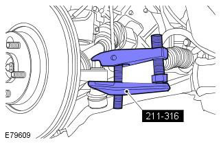
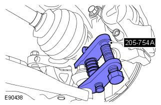
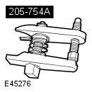 205-754A Splitter, Ball Joints 205-754A Splitter, Ball Joints | 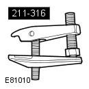 211-316 Separator, Ball Joint 211-316 Separator, Ball Joint |
General Equipment: Powertrain Jack
1. Remove the battery tray. Refer to procedure: Battery installation shelf (414-01 Battery, battery mount and wires, Removal and installation).
2. Raise and support the vehicle.
WARNING: Place secure stands under the vehicle.
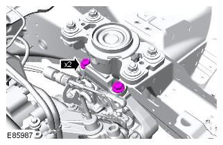
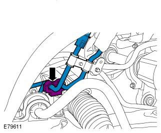
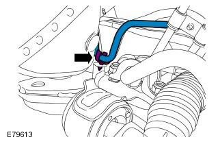
3. Pump out a liquid from a tank of the amplifier of a steering.
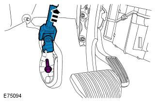
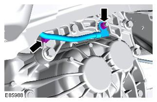
4. Disconnect the bottom section of a steering column from the steering mechanism.
WARNING: Install a new steering column swivel bolt.
5. Remove the gearbox selector. Refer to Procedure: Gear Shift Lever (308-06 Manual transaxle/gearbox external controls, Removal and installation).
6. Remove the starter. Refer to procedure: Starter (303-06B Starting system - 2.2L Duratorq - Td4, Removal and installation).
7. Support the engine.
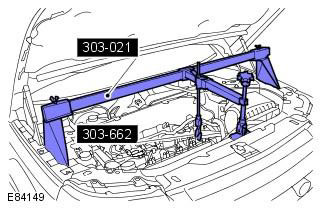
8.
9.
NOTE: If available.

10.
11.
12.
13.
14. Drain the gearbox oil. Refer to Procedure: Draining Transmission Fluid and Refilling Transmission Fluid (308-03 Manual/Transaxle Transmission, General Procedures).
15. Remove the front wheels with tires. Refer to procedure: Wheel and tire (204-04 Wheels and tires, Removal and installation).
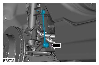
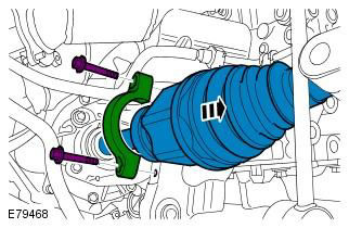
16. Using the special tool, release the left and right tie rod ball joints. Special tool: 211-316
17. Using the special tool, remove the lower arm ball joint. Special tool: 205-754A
18. Disconnect both forward racks from the stabilizer.
CAUTION: Do not allow the ball joint to rotate.
NOTE: Discard 2 nuts.
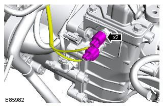
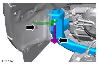
19. Disconnect pressure lines from the steering gear.
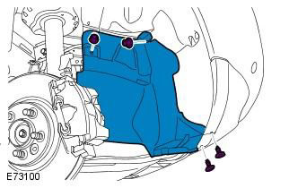
20. Remove both wing mudguard extension panels.
NOTE: The illustration shows the right side, on the left side the procedure is the same.
21. Remove the towing device hole plug.
22. Remove the 2 bolts securing the bumper cover.
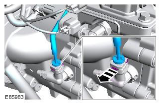
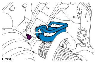
23. Release the power steering lines.
24. Release the fuel line.
CAUTION: Be prepared to collect spilled liquid.
NOTE: Plug all openings.
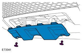
25. Remove the bottom support pad.
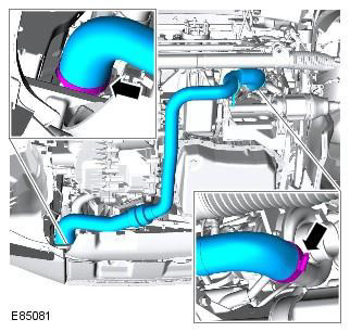
26. Disconnect catalytic converter with a distributive pipe.
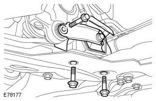
27. Support the subframe. General Equipment: Powertrain Jack
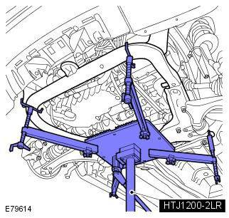
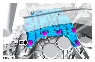
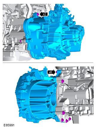
28. Remove the cross member of the front subframe.
CAUTION: Use new subframe bolts.
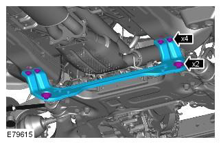
29. Lower the front subframe assembly.
Mark the position of the elements to facilitate subsequent installation. Use new subframe bolts.
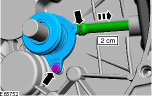
30. Disconnect the left axle shaft.
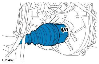
31. Disconnect the right half shaft.
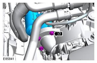
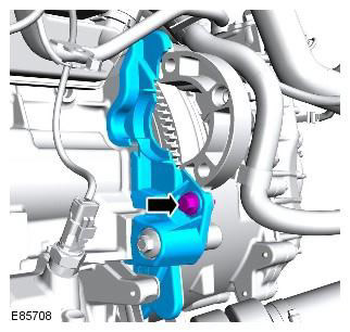
32. Remove the exhaust pipe from the turbocharger.
33.
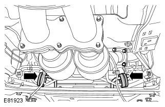
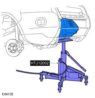
34. Support the gearbox. General Equipment: Powertrain Jack
35.
36.
WARNING: If brake fluid comes into contact with the paintwork, the affected area must be washed immediately with cold water.
Comments on this article