| Item name | Spare part number | Description |
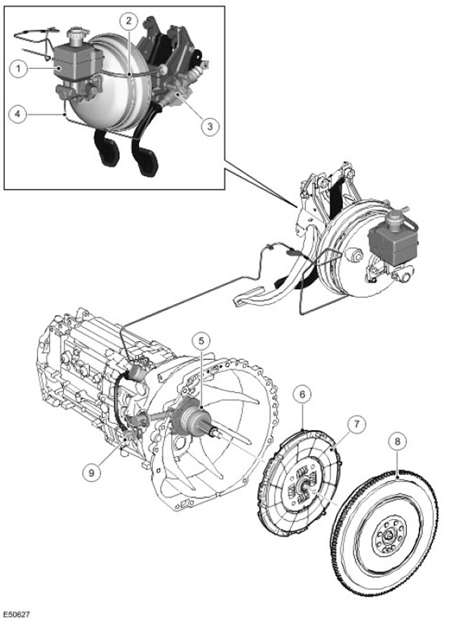
| 1 | - | Common Brake/Clutch Fluid Reservoir |
| 2 | - | Low pressure tube |
| 3 | - | Clutch Master Cylinder |
| 4 | - | high pressure tube |
| 5 | - | Coaxial slave cylinder |
| 6 | - | Clutch cover assy |
| 7 | - | drive disc |
| 8 | - | Double flywheel |
| 9 | - | Release of the coaxial working cylinder |
General information
The operation of the clutch system is based on the well-known principle of hydraulically driving a single driven disc and clutch housing diaphragm spring assembly from the clutch pedal. When the clutch pedal is depressed, hydraulic fluid is pumped through the master cylinder, piping, and slave cylinder, and eventually drives the clutch fingers to disengage the clutch and disengage the actuator and crankshaft. When the foot is removed from the pedal, the spring presses the pressure plate against the driven plate, which, in turn, is pressed against the flywheel. As a result, the crankshaft of the engine engages with the input shaft of the gearbox, forcing them to rotate at the same speed.
The clutch system has a conventional design and includes the following main components:
- Clutch Master Cylinder
- Clutch Pressure Pipes
- Clutch release bearing/slave cylinder
- Clutch cover assy
- Driven clutch disc
- Double flywheel
Clutch Master Cylinder
| Item name | Spare part number | Description |
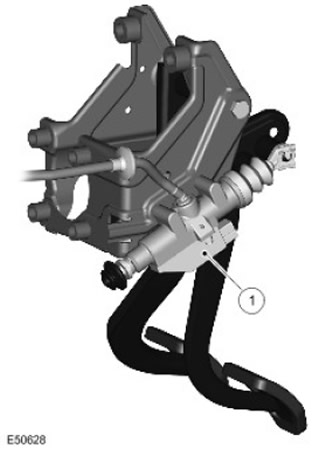
| 1 | - | Clutch Master Cylinder |
The clutch master cylinder is attached directly to the pedal box assembly located in the footwell on the driver's side.
The cylinder contains a piston assembly with a rod connected to the clutch pedal and spring. When depressed, the clutch pedal pushes the piston through the linkage. Pressing the pedal further increases the pressure in the cylinder and pipelines.
The cylinder has 2 hydraulic connections:
- With low pressure supply tube (through which fluid is supplied from the brake fluid reservoir)
- With high pressure tube
The pedal travel is limited by the upper and lower stops built into the master cylinder.
Low pressure tube
The low pressure tube is a plastic tube that runs between the master cylinder and the common (combined) brake fluid reservoir. This tube ensures that the hydraulic system is constantly filled with fluid. The tubing is connected at each end using push type tubing connectors.
High pressure pipes
The high pressure pipes are routed on the right side of the vehicle, from the clutch master cylinder to a location near the transmission clutch housing. The tube assembly includes a steel piping and a flexible tube. The flexible tube absorbs vibrations between the metal tubes attached to the car body and the transmission.
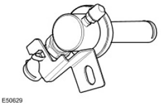
A vibration damper is installed in the tube. The shock absorber is located at the front end of the transmission tunnel on the right side of the vehicle and is attached to a bracket on the body.
The connection of high pressure pipes is carried out using quick connectors with a U-shaped fixing spring clip.
Release of the coaxial working cylinder assy
The outlet of the co-axial slave cylinder assembly connects the external piping to the clutch release system built into the clutch housing. The mounting bracket ensures proper orientation of the assembly. A seal is provided between the assembly and the clutch housing. The bleed valve is located in the same place.
Coaxial slave cylinder
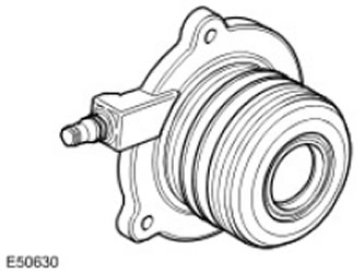
The coaxial slave cylinder assembly consists of a clutch release bearing and a hydraulic slave cylinder. The entire assembly is attached to the front of the gearbox with 3 bolts. The bolts are arranged asymmetrically, which ensures the required angular position of the working cylinder, which, moreover, is centered by a collar. In the free state, the slave cylinder is fully extended, and after installing the clutch housing on the engine, it automatically assumes the correct position. The node does not need any tuning or adjustment.
Clutch cover assy
The clutch cover assembly is also referred to as self-adjusting clutch. Its nominal diameter is 260 mm.
Self adjusting clutch

| Item name | Spare part number | Description |
| A | - | Conventional clutch |
| B | - | Self adjusting clutch |
| 1 | - | Sensor springs |
| 2 | - | Regulator ring |
| 3 | - | diaphragm spring |
The Self-Adjusting Clutch incorporates a mechanism that improves system performance and rider comfort by providing more consistent pedal force as friction surfaces wear, unlike a conventional clutch type that requires more pedal force as it wears.
In a conventional clutch design, surface wear causes the angle of the driving diaphragm spring to change as the clutch pressure plate moves axially toward the engine, resulting in more force required to engage the clutch (diaphragm driving force varies with diaphragm angle). A self-adjusting clutch minimizes this disadvantage by allowing the diaphragm spring to follow the axial movement of the pressure plate and thereby maintaining the same diaphragm spring angle throughout the life of the clutch. Along with the stabilization of the force on the pedals, the clamping force on the pressure plate also remains constant as it wears.
The diaphragm spring is not fixed at a pivot point as in conventional systems, but pivots between the sensor spring and the regulator ring. The sensor spring generates an opposing force that is only sufficient to keep the diaphragm spring, via the adjuster ring, axial to the housing during normal clutch engagement. As the friction linings wear, the desire to change the angle of the diaphragm entails an increase in the engagement force required to actuate the clutch. When this increased force begins to exceed the opposing force of the sensor spring, the diaphragm spring moves axially towards the pressure plate, restoring the original angle. In this state, the required closing force is reduced to the value of the counter spring force of the sensor, balancing the diaphragm spring in the new position.
During the axial movement of the diaphragm spring, the adjuster ring travels an increased distance between the spring and the casing. The ring has protruding segments with an inclined profile that fit into the corresponding recesses of the clutch housing. When the diaphragm spring is displaced axially to compensate for wear, the 3 preloaded coil springs in the clutch housing cause the adjuster ring to rotate, lifting the lugs and providing additional distance between the diaphragm spring and the clutch housing.
NOTE: During operation, the regulator ring turns clockwise (when handled from the gearbox side). If a worn driven disc is replaced during operation and the clutch cover assembly is left the same for any reason, the adjuster ring must be turned back to the preload position. This operation requires a press to relieve the load on the clutch while the adjuster ring is being repositioned and is therefore not recommended during maintenance. When performing any repair, it is recommended to replace the clutch cover assembly and driven disc together.
NOTE: If for any reason the clutch cover and driven plate have been removed and the driven plate is then determined to be serviceable, the original cover/driven plate can be reinstalled without any adjustment.
Clutch drive
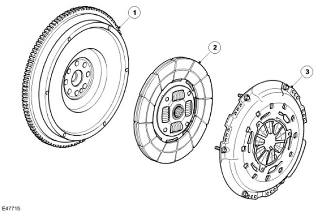
| Item name | Spare part number | Description |
| 1 | - | Double flywheel |
| 2 | - | drive disc |
| 3 | - | pressure plate |
The clutch disc has a traditional splined sleeve design to position the primary spline of the gearbox. The connection point does not need lubrication. The lead-free and asbestos-free friction material is linked to the bushing by a spring pack that reduces the transmission of torsional force to the gearbox.
Double flywheel
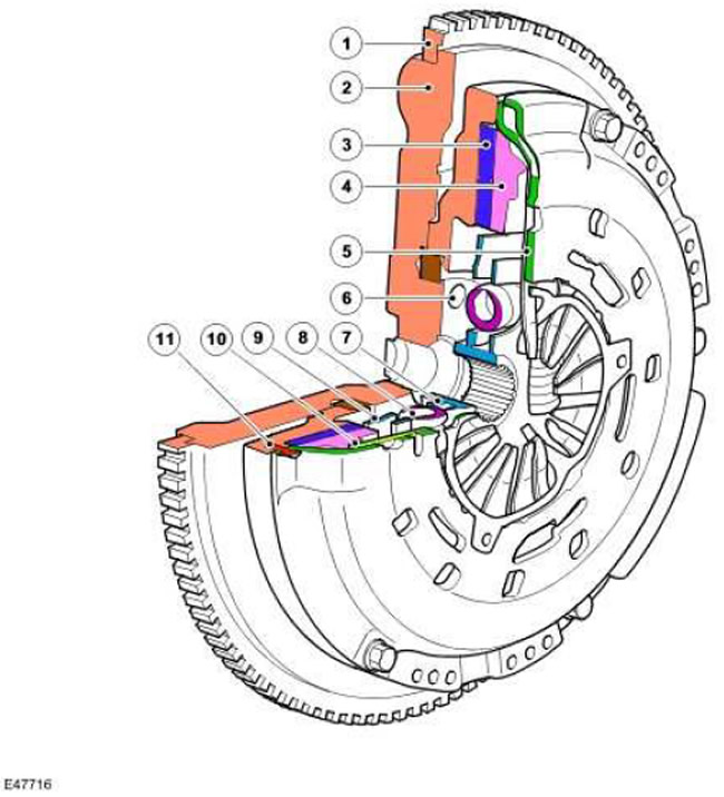
| Item name | Spare part number | Description |
| 1 | - | ring gear |
| 2 | - | primary flywheel |
| 3 | - | Internal drive disc |
| 4 | - | Spring housing |
| 5 | - | Lid |
| 6 | - | Mounting hole |
| 7 | - | splined bushing |
| 8 | - | Damping springs |
| 9 | - | Internal drive disc |
| 10 | - | Spring housing |
| 11 | - | secondary flywheel |
In accordance with the name, this assembly consists of two main sections: the primary, which is fixed to the crankshaft using 8 fasteners, and the secondary, to which the clutch cover assembly is attached.
The primary section moves the starter ring gear and roller bearing into which the transmission's long input shaft is inserted.
The secondary section forms the contact surface for the clutch lining and is secured with 3 pins and 6 mounting holes that are used to attach the clutch housing to the flywheel.
If the flywheel is removed or replaced, it is recommended to use new crankshaft fasteners.
The secondary section is supported by a bearing and radial springs in the primary section.
Free rotation of parts between primary and secondary sections (by the masses) produces a shock-absorbing effect, reducing the amplitude of torsional vibrations between the crankshaft and the gearbox.
Comments on this article