Dismantling
1. Put the car on a lift.
2. Raise the rear of the vehicle.
WARNING: Do not work under a vehicle raised only on a jack or lift. Always install safety props.
3. Remove rear wheels.
4. Release the air from the air suspension system.
REAR SUSPENSION, ADJUSTMENTS, Pneumatic suspension - air release and filling the system with air.
5. Remove the rear driveshaft.
DRIVE SHAFTS, REPAIR WORKS, Cardan shaft - rear.
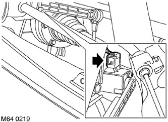
6. Disconnect the multi-pin electrical connectors for the rear body height sensors.
7. Remove the Allen type screws that secure the brake hose clamps to the upper suspension arms.
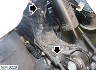
8. Loosen the clamps of the electrical wiring of the wheel speed sensors and the brake pad wear sensors to the upper suspension arms and the body.
9. Release the hose clamps of the air suspension system hoses to the body.
10. Place a jack as a support under the lower control arm.
CAUTION: Do not leave the lower control arm suspended from the air spring.
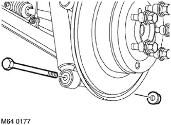
11. Turn away bolts of fastening of shock-absorbers to the bottom levers.
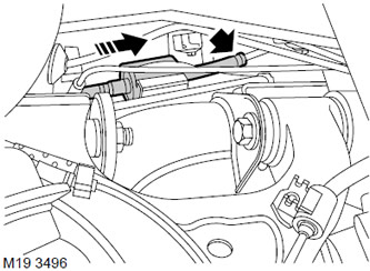
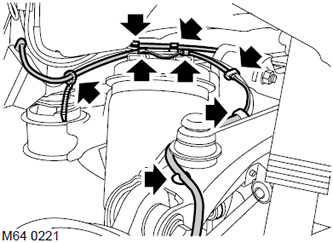
12. Remove the fuel coolant heater and fuel pump from the rubber mounts.
13. Place a jack as a support under the rear subframe.
14. Turn away 2 bolts of fastening of a stretcher which are located on a diagonal from opposite sides. Remove the Belleville washer and exhaust pipe mounting bracket. Slide the cup washer and exhaust pipe mounting bracket onto the support bolts. Use the support bolts as props for the subframe.
15. Screw the bolts onto the subframe by hand. Wrap the bolts to a depth of at least 16 mm.
16. Turn away 2 remained bolts of fastening of a stretcher.
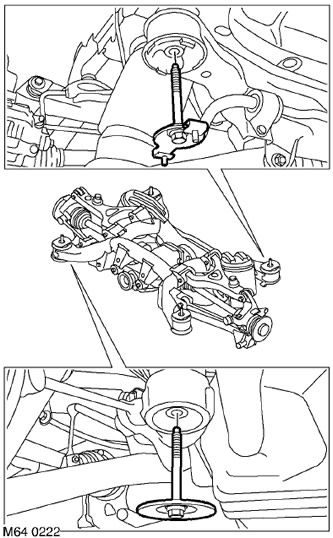
17. Lower the subframe to provide access to the bushings.
18. Remove the slotted rings from the supports.
19. Mark the location of the bushing on the subframe. To do this, paint a mark on the stretcher.
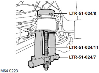
20. Assemble tool LRT-51-024/7.
21. Install the LRT-51-024/8 puller on the bushing and the LRT-51-024/7 tool on the subframe. Screw the LRT-51-024/11 screw into the LRT-51-024/8 tool, align the tool and remove the sleeve.
Assembly
1. Clean the bushing and its seating surface of dirt.
2. Apply rubber grease to the new bushing and bushing bore.
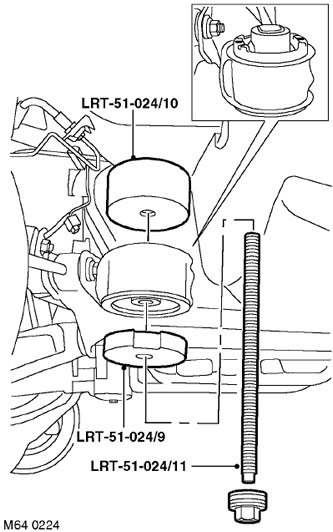
3. Install the tool LRT-51-024/10 on the subframe, which is designed for mounting bushings.
4. Slide tool LRT-51-024/9 onto stud LRT-51-024/11 and slide new bushing over it.
5. Screw the pin LRT-51-024/11 into tool LRT-51-024/10.
6. Turn the sleeve so that its alignment mark coincides with the mark applied with paint on the subframe.
7. Install the sleeve and remove the tool.
8. Repeat the procedure for the sleeve located diagonally on the opposite side of the subframe.
9. Raise the subframe to the body and unscrew the support bolts. Insert the bolts through the bushings located on opposite sides and screw them on by hand.
10. Lower the subframe.
11. Remove and replace remaining bushings.
12. Install the two slotted rings on their respective bushings. Raise the subframe of the body so that there is a small gap for installing the remaining rings.
13. Install the Belleville washer and exhaust pipe bracket, tighten the two bolts, do not completely tighten them yet.
14. Remove the support bolts from the subframe and remove the Belleville washer and exhaust pipe bracket.
15. Install the Belleville washer and exhaust pipe bracket with the remaining subframe mounting bolts. Install the rings on the bushings and screw the bolts to the subframe.
16. Install the subframe on the pins.
17. Tighten the subframe mounting bolts with a torque of 165 Nm (122 lb ft). Before tightening the bolts, make sure that the slotted rings are in the correct position with respect to the bushings.
18. Establish the fuel pump on support.
19. Wrap bolts of fastening of shock-absorbers to the bottom levers. Do not tighten the bolts yet completely.
20. Fix the hoses of the air suspension system to the body.
CAUTION: Make sure that the location of the hose alignment marks matches the location of the clamps.
21. Fix the wiring of the wheel speed sensors and brake pad wear sensors.
22. Reinstall the brake hoses and secure their clamps.
23. Connect multicontact sockets of gauges of height of provision of a body.
24. Install the rear driveshaft.
DRIVE SHAFTS, REPAIR WORKS, Cardan shaft - rear.
25. Bring the pressure in the air suspension system to the nominal value.
26. Reinstall the rear wheels and tighten the nuts to 140 Nm (103 lb ft).
27. Tighten the bolts of the shock absorbers to the lower arms with a torque of 110 Nm (81 lb ft).
Comments on this article