Contents: Removal ⇩ Installation ⇩
Before disconnecting the battery, carefully read the "Disconnecting the Battery" section and follow all instructions therein.
GENERAL INFORMATION, Precautions when working with electrical equipment.
Removal
1. Remove all fuel from the tank.
V8 ENGINE FUEL SUPPLY SYSTEM, ADJUSTMENTS, Removing fuel from the fuel tank.
2. Disconnect the ground cable from the battery.
CAUTION: Before disconnecting the battery, make sure the key is removed from the ignition. If you forget to remove the key from the ignition, the computer will remember the fuel gauge reading before disconnecting the battery and will display the previous value when the battery is reconnected.
Original article on the web portal [LRMAN.ru]
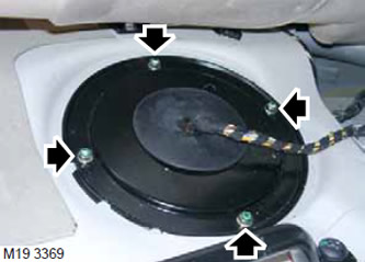
3. Unscrew 4 nuts and remove the right body cover to access the fuel tank.
WARNING: Fuel vapors are highly flammable and in a confined space they are also toxic and explosive. A fire extinguisher must be available in the room where fuel is removed from the fuel tank. (foam, carbon dioxide, gas or powder).
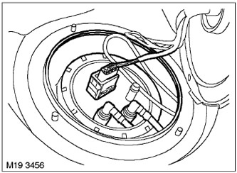
4. Disconnect the connector from the fuel pump.
5. Prepare a suitable container for draining the remaining fuel.
WARNING: Fuel leakage is inevitable during this operation. Take safety measures to prevent fire or explosion.
6. Having noted the location of the fuel hoses, disconnect the pressure and drain lines from the fuel pump.
CAUTION: Before disconnecting any system components, make sure that the areas immediately adjacent to the components to be disconnected are free of dirt. Close open ends of pipes with plugs immediately after disconnection to prevent foreign particles from entering the system.
7. Tie the lines together and move them aside so as not to interfere with the removal of the fuel pump.
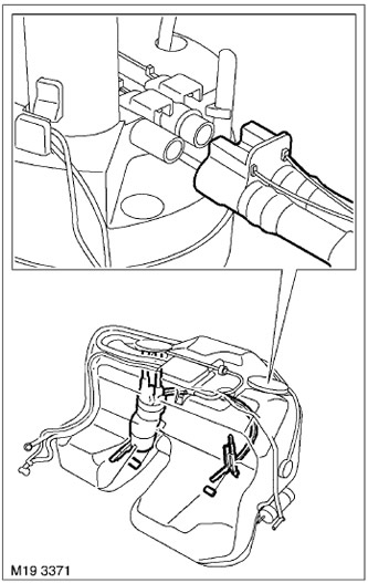
8. Disconnect the coupling from the fuel pump through the left inspection hole of the fuel tank. The coupling is made together with the electrical connector.
9. Clean the surface of the lock ring from dirt and dust.
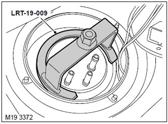
10. Using the LRT-19-009 tool, remove the lock ring from the fuel tank body.
11. Carefully remove the fuel pump from the tank. When reinstalling, replace the old pump seal with a new one.
12. Prepare a suitable container for draining the remaining fuel.
13. Disconnect the left fuel level sensor and remove it from the tank.
Installation
1. Clean the surfaces adjacent to the fuel tank inspection holes from dirt and dust.
2. Clean the fuel pump housing and install a new sealing gasket.
3. Connect the connecting coupling of the pipeline coming from the left fuel level sensor to the fuel pump. The coupling is made together with the electrical connector of the sensor.
CAUTION: After connection, the coupling lock must be in the "assembled" position.
4. Carefully insert the fuel pump into the fuel tank. Install it in the correct position, do not allow the seal to become skewed. Using the left inspection hole, check the position of the lower end of the pump.
5. Using tool LRT-19-009, install the lock ring and tighten it to 35 N·m (26 ft·lbs).
6. Connect the fuel hoses to the fuel pump.
7. Drain the fuel from the container and prepare it for further use.
8. Connect the electrical connector to the fuel pump.
9. Reinstall the right fuel tank access cover and tighten the retaining nuts to 10 N·m (7 lb ft).
10. Connect the ground cable of the battery.
11. Fill the fuel tank.
V8 ENGINE FUEL SUPPLY SYSTEM, ADJUSTMENTS, Removing fuel from the fuel tank.
12. Connect the TestBook/T4 diagnostic tool and check that the new fuel level sensors are working properly.
Comments on this article