Review
The steering column switches include the steering column multifunction switch and the ignition switch. Both the switch and the ignition switch are located on the steering column assembly.
The steering column multifunction switch is a housing that houses the turn signal lever assembly and the wiper control lever assembly. The multi-function switch is located behind the steering wheel and attaches to the steering column assembly from above and to the steering column lock housing from below.
Turn signal switch
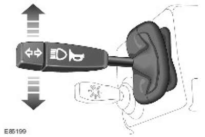
The turn signal switch assembly is located on the left side of the case. The switch is connected to the main wiring harness using a connector on the back of the switch. The lever performs the following functions:
- Switching on the left / right turn signal
- Switching low / high beam headlights
- High beam signaling
- Sound signal
The inclusion of the right direction indicators is performed by moving the lever up, and the inclusion of the left direction indicators is performed by moving the lever down. The lever is fixed in the selected position and remains in it until it is returned to the central position corresponding to turning off the direction indicators. The positions of the lever when turning on the left and right direction indicators are connected by separate wires to the alarm relay through the alarm light switch. When the lever is moved, the circuit in the alarm relay closes to «mass» through the contacts in the lever installed in the selected position. The alarm relay senses the circuit is closed and turns on the corresponding direction indicators, which operate until the lever returns to the center position, corresponding to turning off the direction indicators. The direction indicators are turned off either manually (driver), or automatically when the steering wheel is returned to the straight ahead position.
Switching low / high beam headlights and signaling high beam headlights
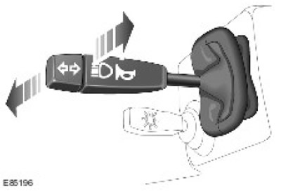
High beam headlights are switched on by moving the lever forward (from the driver). The lever is locked in this position and the high beams remain on until the lever is manually moved back. To signal the high beam headlights, the lever must be moved back (to the driver). The switch contacts complete the electrical circuit and the headlights remain on as long as the lever is in the specified position. This position of the lever is not fixed and the high beam used for signaling turns off when the driver releases the lever and the lever returns to the center position. The contacts responsible for turning on the high beam of the headlights and signaling the high beam of the headlights are connected to the high / low beam relay and «weight» through different wires. When the lever is moved, the high/low beam relay circuit closes to «mass» through the contacts of the lever installed in the selected position.
Wiper/Washer Switch Assembly
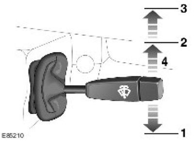
| Pos. | spare part no | Name |
| 1 | - | Intermittent cleaning |
| 2 | - | Low operating speed |
| 3 | - | High operating speed |
| 4 | - | One wiper |
The various functions of the windshield wiper are switched on by moving the lever up or down. The one-time windshield wipe mode is activated by pushing the spring-loaded switch up. The switch contact corresponding to the single cleaning mode is connected by one wire to the delay timer of the electronic control unit (ECU) and with "weight". When the lever is moved, the ECU delay timer circuit closes to «mass». If the circuit is closed, the wipers operate as long as contact is maintained in the switch.
Switching on the intermittent wiper operation is carried out by moving the lever down to the first fixed position. The duration of the cleaning cycle in intermittent operation is controlled by the ECU delay timer. The wiper operates intermittently until the lever is moved to the wiper off, constant low speed, or high speed position. The lever contact corresponding to intermittent operation is connected to the ECU delay timer and «weight». When the lever is moved to the position corresponding to intermittent operation, the circuit is closed. If the circuit is closed, the wipers operate intermittently as long as contact is maintained in the switch.
The inclusion of a constant mode of operation of the windshield wiper at low speed is carried out by moving the lever up to the second fixed position. Wiper operation in this mode continues until the lever is moved to one of the following positions: wiper off, wiper on in intermittent mode, wiper on at high speed. The lever pin corresponding to this mode is connected to the ECU delay timer and «weight». When the lever is moved to the position corresponding to the windshield wiper at low speed, the circuit is completed. If the circuit is closed, the wipers operate at low speed as long as contact is maintained in the switch.
The inclusion of a constant mode of operation of the windshield wiper at high speed is carried out by moving the lever up to the second fixed position. The operation of the purifier in this mode continues until the lever is moved to one of the following positions: purifier off, purifier on in intermittent mode, purifier on at low speed. The lever pin corresponding to the high speed operation mode is connected to the ECU delay timer and «weight». When the lever is moved to the position corresponding to turning on the cleaner at high speed, the circuit is closed. If the circuit is closed, the wipers operate at high speed as long as contact is maintained in the switch.
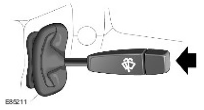
The windshield washers are activated by pressing a button on the end of the washer/wiper stalk on the right side of the steering column. When the button is pressed, the washers come on immediately and run until the button is released. The washer button contact is connected to the ECU delay timer and «weight». When the button is pressed, the circuit is closed. If the circuit is closed, the washers operate as long as contact is maintained.
Egnition lock
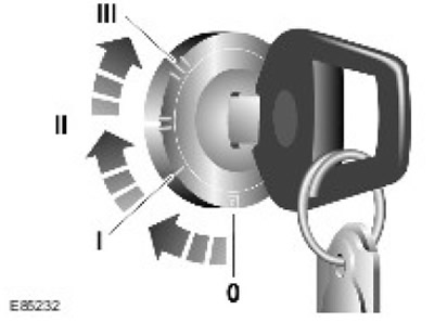
The ignition switch is located to the left of the steering column assembly. The lock is attached to the molded housing of the steering column lock with two latches that fit into the corresponding slots in the housing.
The ignition lock has a hole for the drive shaft. The drive shaft passes through the steering column lock. The shaft is driven by the driver when he turns the ignition key. The rotation is transmitted to the drum in the ignition lock, and two contacts located on the drum close the circuit in accordance with the position of the key in the ignition lock. In each of the three positions of the ignition lock, a spring-loaded ball enters the seat. This is done so that the driver feels that the required key position in the ignition switch has been reached.
Comments on this article