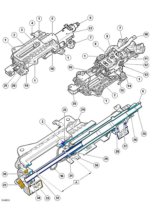
| Item name | Spare part catalog number | Description |
| A | - | The compression stroke during a crash is 120.00 mm |
| 1 | - | Mounting holes |
| 2 | - | Upper bracket |
| 3 | - | Screw |
| 4 | - | Fixing hook |
| 5 | - | U-bracket |
| 6 | - | Steering wheel splines |
| 7 | - | Complete lock |
| 8 | - | Cam disc |
| 9 | - | Cam disc assembly |
| 10 | - | Adjustment lever |
| 11 | - | Brake shoe |
| 12 | - | Lever Nut |
| 13 | - | Lever bolt |
| 14 | - | Shear capsule (2 pcs.) |
| 15 | - | Cam disc assembly |
| 16 | - | Adjusting balance spring (2 pcs.) |
| 17 | - | Main building |
| 18 | - | Tape (2 pcs.) |
| 19 | - | Steering wheel angle sensor |
| 20 | - | Hinge pin |
| 21 | - | Hinge housing |
| 22 | - | Crosspiece |
| 23 | - | Sleeve |
| 24 | - | Thrust washer (2 pcs.) |
| 25 | - | Upper shaft |
| 26 | - | Upper bearing |
| 27 | - | Ferrule |
| 28 | - | Locking coupling |
| 29 | - | Intermediate bearing |
| 30 | - | Spring |
| 31 | - | Spring washer |
| 32 | - | Lower shaft |
| 33 | - | Retaining ring |
| 34 | - | Cardan joint seal |
| 35 | - | Pivot fork |
| 36 | - | Leading flange |
The steering column is secured to the inner crossmember with four 8mm low-taper head Torx self-tapping screws. The two front mounting screws pass through the steering column support bracket, and the two rear mounting screws also pass through the shear capsules. In the event of a severe frontal impact, the shear capsules remain stationary on the crossmember, and the U-bracket (together with the main body) detaches from the capsules, which allows the column to shorten its length along the axis (fold), while the ring bands absorb energy without transferring it completely to the driver.
CAUTION: Be careful when handling the steering column to avoid pinching your fingers when removing the adjusting lever during the removal procedure when the column is removed from the vehicle. The balance springs will cause the column to rise quickly to the up position.
The column has a magnesium alloy upper bracket that is attached to the vehicle's crossmember. The upper bracket holds the hinge housing, U-shaped bracket, upper and lower shafts, and the main body. The upper bracket has two hooks that fit into the inner crossmember's grooves. The hooks help support the steering column during removal and installation.
The hinge housing is attached to the front of the upper bracket by two hinge pins. The hinge housing allows the tilt of the steering column to be adjusted and contains the bearing on which the lower shaft of the column rests.
The U-bracket is secured to the top bracket with a screw, bushing, and plastic washer. (third mount) into the slots in the top of the upper bracket. When the column is installed in the vehicle, the shear capsules that attach to the U-shaped bracket are pressed against the upper bracket with screws, which prevents the U-shaped bracket from moving. The bolts also pass through rectangular steel strips that are twisted around a plastic bushing on one side. (mounted on a shear capsule). The bands are used to control the rate at which the steering column compresses in the event of a severe frontal collision.
The main body is mounted on the U-shaped bracket by means of a lever bolt. The bolt is fixed in the vertical slots of the U-shaped bracket and the horizontal slots of the main body. The bolt also passes through the clamping plates. (one on each side of the U-bracket). The housing contains the intermediate and upper bearings through which the upper shaft passes. Two offset holes in the main housing provide mounting for the steering column lock assembly.
The upper and lower shafts run along the column assembly. The upper shaft rests on two bearings in the main body, and the lower shaft is inserted into the upper shaft and rests on a bearing in the hinge housing. The lower shaft has a tubular section with external splines. These splines engage with the internal splines of the upper shaft. The splines transmit the rotation of the upper shaft to the lower shaft. In this case, the shafts can move telescopically relative to each other. The length of the splined parts providing linear movement is 120 mm. The lower shaft has a universal joint crosspiece for attaching the steering fork. The steering fork is attached to the intermediate shaft of the steering column on the inside of the bulkhead using a special cam bolt and a self-locking nut.
The steering angle sensor is attached to the steering column joint housing and its central pinion is driven by a drive flange that is attached to the lower shaft and rotates with the steering wheel. The sensor transmits the steering angle value via the high-speed CAN bus, to which various vehicle systems are connected. The steering angle sensor becomes disconnected from the column during a frontal impact. When working on the steering column assembly, be careful not to accidentally damage the sensor. For more information, refer to Anti-Lock Control -Traction Control (206-09A).
The upper shaft has a locking sleeve that engages with the locking bolt of the column lock assembly. The locking sleeve is secured to the shaft by a safety ring. The safety ring ensures that the shaft slips when a certain force is exceeded. This prevents damage to the column lock as a result of excessive force being applied to the steering wheel. The safety ring ensures that the upper shaft slips when the torque exceeds 200 Nm. The torque must exceed 100 Nm to further rotate the locking sleeve.
The steering column is height and tilt adjustable. The column adjustment range in the longitudinal direction is 40 mm, and in the tilt angle - 6°. The adjustment mechanism includes an adjustment lever, a cam washer, a bolt and a nut of the lever, two brake shoes and two clamping plates in the assembly.
The plastic adjustment lever is mounted on the underside of the steering column and is attached to the cam washer. When the lever is moved downwards, the cam washer rotates and relieves the pressure on the lever bolt. The lever bolt also passes through two clamping plates in the assembly. When the lever is moved upwards, the cam washer rotates and applies pressure to the lever bolt, which transmits pressure to the brake shoes. The shoes, in turn, press the clamping plates in the assembly, fixing the column in the required position. The lever bolt is secured with a self-locking lever nut, which rests on a support bearing.
CAUTION: Under no circumstances should the lever nut be loosened, as this will reduce the effectiveness of the adjuster mechanism, which will affect the stability of the column during a frontal collision.
The hinge housing is attached to the upper bracket by two hinge pins. When adjusting the tilt of the column, the hinge housing rotates relative to the hinge pins, raising and lowering the column. At the same time, it maintains a constant position relative to the upper bracket. An adjusting spring is installed between the U-shaped bracket and the main housing, compensating for the weight of the main housing, upper shaft, steering wheel and airbag. It prevents the steering wheel from dropping quickly when the adjustment lever is released.
In the event of a serious frontal collision, the upper part of the column assembly folds along the axis, which reduces the traumatic impact on the driver. Controlled column folding is ensured by the joint operation of a number of units and components. The following units and components are involved in the controlled folding of the steering column:
- Thrust washer and bushing (third mount)
- Shear capsules
- Ribbons
- Splined connection of the upper and lower shafts
The shear capsules have central holes through which the rear mounting bolts are inserted into the upper bracket. The capsules are attached to the U-shaped bracket with conical grooves, which have small cutouts on the inner surface. The shear capsules have small diameter holes that coincide with the cutouts on the U-shaped bracket. When installing the capsules, the holes and cutouts are filled with plastic. The plastic fastening of the capsules provides a controlled initial force for breaking the column in a collision. If the displacement is more than 10 mm, the U-shaped bracket is no longer held by the shear capsules. When working on the steering column, be careful not to damage or displace the shear capsules.
The pressure of the "third fastening" screw is applied to the upper bracket (through the bushing and compression washers). In the event of a collision, this load (in addition to the resistance of the shear capsules) must be overcome before the steering column collapses. If this load is exceeded, (and offsetting the mount by 20 mm) the column easily moves in the groove of the upper bracket, folding in the required direction. Under no circumstances should the tightening torque of the screw be changed.
The tapes are made of rectangular steel. One end is twisted around a plastic sleeve mounted on a shear capsule. The other end forms a hook that fits into a groove in a U-shaped bracket.
If, in the event of a collision, the U-bracket is displaced relative to the shear capsules by 8 mm, the tapes begin to unwind as a result of the movement of the U-bracket. The tapes provide the main absorption of energy when the column collapses. The cross-section of the tapes changes after stretching by approximately 40 mm, allowing the amount of energy absorbed to be adjusted.
Comments on this article