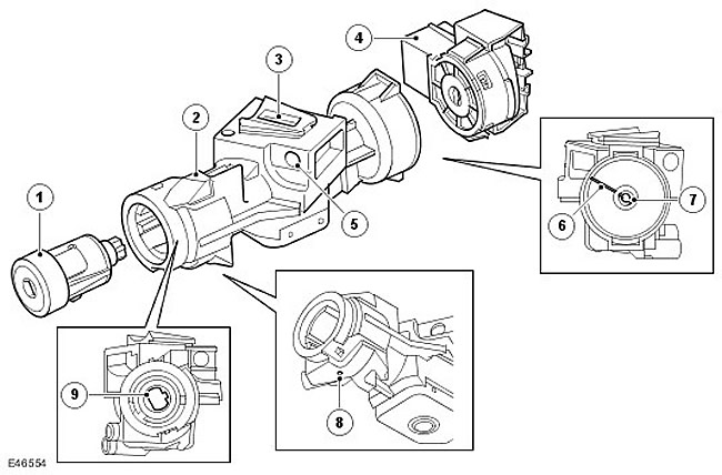
| Item name | Spare part catalog number | Description |
| 1 | - | Lock cylinder |
| 2 | - | Steering column lock assembly |
| 3 | - | Locking bolt |
| 4 | - | Ignition switch |
| 5 | - | Mounting hole |
| 6 | - | Label |
| 7 | - | Lock drive |
| 8 | - | Cylinder release hole |
| 9 | - | Cylinder drive |
The steering column lock has a cast housing that contains the locking mechanism. The assembly is sealed with a cover that is secured with cylindrical pins inserted into blind holes. The steering column lock is not repairable and should be replaced as a single unit. The lock has a locking bolt that moves up and down on a cam. The cam is part of the shaft that passes through the lock and is driven by turning the ignition key in the ignition switch.
The steering column lock is attached to the steering column with two shear bolts. When installing the lock on the steering column, the bolts are tightened to a specified torque at which their heads are sheared. This complicates the removal of the steering column lock.
CAUTION: Before removing the ignition switch and/or lock cylinder, make sure the lock is in position I. When removing the lock from the steering column, make sure that the shaft does not turn. If the shaft turns when the key is not in position 0, the plunger with the spring may come out of the locking bolt, causing the steering column lock to not function properly. If the plunger is not positioned correctly in the locking bolt, the lock is unserviceable and must be discarded.
The ignition lock cylinder is located on the right side of the steering column lock. The lock is seated in a hole and locked in place. To remove and install the cylinder, insert the ignition key into the cylinder and turn the key to position I. To remove the cylinder from the steering column lock, insert a suitable pin into the release hole to depress the lock plunger on the lock cylinder. The cylinder can then be removed from the lock using the key.
The ignition switch is installed on the left side of the steering column lock. The ignition switch is seated in a hole and held in place by two plastic clips located in the grooves of the steering column lock. To remove the ignition switch, make sure that the key is in the lock cylinder and set to position I, then press the two plastic clips and remove the ignition switch from the steering column lock. Before replacing the lock cylinder, make sure that the lock is in position I (the new lock is supplied set to position 0), and also that the drive tabs on the lock shaft are aligned with the marks on the steering column lock housing. Press and seat the ignition switch into the steering column lock, ensuring that it is fully engaged with the drive tabs and that the plastic clips are fully seated in the grooves.
Comments on this article