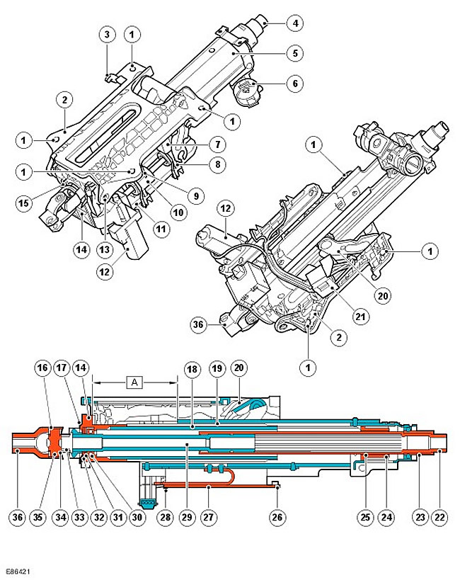
| Item name | Spare part catalog number | Description |
| A | - | The compression stroke during an accident is 90.00 mm |
| 1 | - | Mounting hole |
| 2 | - | Upper bracket |
| 3 | - | Fixing hook |
| 4 | - | Steering wheel splines |
| 5 | - | External profile |
| 6 | - | Complete lock |
| 7 | - | Steering column tilt solenoid |
| 8 | - | Steering column tilt device coupling |
| 9 | - | Steering column longitudinal adjustment solenoid |
| 10 | - | Coupling of the longitudinal adjustment device of the steering column |
| 11 | - | Potentiometer |
| 12 | - | Electric motor |
| 13 | - | Hinge pin |
| 14 | - | Hinge housing |
| 15 | - | Steering wheel angle sensor |
| 16 | - | Needle roller bearing |
| 17 | - | Leading flange |
| 18 | - | Internal profile |
| 19 | - | Emergency beam |
| 20 | - | Tilt lever |
| 21 | - | Electrical connector |
| 22 | - | Upper shaft |
| 23 | - | Upper bearing |
| 24 | - | Locking coupling |
| 25 | - | Ferrule |
| 26 | - | Casing fastening clamp |
| 27 | - | Ribbon |
| 28 | - | shear pin |
| 29 | - | Lower shaft |
| 30 | - | Lower bearing |
| 31 | - | Washer |
| 32 | - | Retaining ring |
| 33 | - | Clamp |
| 34 | - | Cardan joint seal |
| 35 | - | Crosspiece |
| 36 | - | Pivot fork |
An electrically adjustable steering column is standard on certain models and available on other models as an option.
The steering column is secured to the inner crossmember with four 8mm low-taper head Torx self-tapping screws. In the event of a severe frontal impact, the strap and shear pin on the underside of the column provide a controlled collapse of the outer housing relative to the inner housing, allowing the column to shorten its axial length (collapse), absorbing energy without transferring it entirely to the driver.
The column has a magnesium alloy upper bracket that is attached to the vehicle's crossmember. The upper bracket houses the hinge housing, outer housing, and upper and lower shafts. The upper bracket has two hooks that fit into the inner crossmember's grooves. The hooks help support the steering column during removal and installation.
The tilt lever is mounted on an external aluminum profile, in which the steel adapter of the steering column lock is fixed (with upper bearing). The inner profile is installed inside the outer profile on two longitudinal holders, allowing telescopic movement of the steering column to adjust its longitudinal position.
The upper and lower shaft assemblies are located inside the column on bearings in the steering column lock adapter and the hinge housing. Both shafts are of tubular construction. The lower shaft has external splines. (nylon pressed). These splines engage with internal splines in the upper shaft. The splines transmit the rotation of the upper shaft to the lower shaft. In addition, the shafts can telescopically move relative to each other during axial folding of the column. The lower shaft has a universal joint crosspiece for attaching the steering fork. The steering fork is attached to the intermediate shaft of the steering column on the inside of the partition using a special cam bolt and a self-locking nut.
The steering angle sensor is attached to the steering column joint housing and its central pinion is driven by a drive flange that is attached to the lower shaft and rotates with the steering wheel. The sensor transmits the steering angle value via the high-speed CAN bus, to which various vehicle systems are connected. The steering angle sensor becomes disconnected from the column during a frontal impact. When working on the steering column assembly, be careful not to accidentally damage the sensor. For more information, refer to Anti-Lock Control -Traction Control (206-09A).
The upper shaft has a locking sleeve that engages with the locking bolt of the column lock assembly. The locking sleeve is secured to the shaft by a safety ring. The safety ring ensures that the shaft slips when a certain force is exceeded. This prevents damage to the column lock as a result of applying excessive force to the steering wheel when the lock is locked. The safety ring ensures that the upper shaft slips when the torque exceeds 200 Nm. The torque must exceed 100 Nm to further rotate the locking sleeve.
The electric steering column adjustment unit can adjust the tilt and fore-aft position of the steering column. The column can be adjusted by 40.00 mm in height and 6 degrees in tilt. The adjustment mechanism consists of an electric motor, a lead screw, a steering column tilt solenoid, a steering column fore-aft solenoid, a steering column tilt coupling, and a steering column fore-aft coupling.
The steering column position is adjusted by the driver using the joystick located to the left of the steering column cover. Moving the joystick forward and backward changes the longitudinal adjustment of the steering column accordingly, and moving the joystick up and down changes the tilt of the steering column accordingly. The same electric motor is used for both types of adjustment. The control lever supplies voltage to one or another solenoid, which, in turn, engages with the corresponding clutch on the lead screw.
If the "Auto" function is selected on the joystick, the steering column will rise to the highest position when the key is removed from the steering column lock cylinder and will return to its previous position when the key is reinserted.
When adjusting the steering column longitudinally, the lead screw moves the outer housing forward or backward. When changing the tilt of the steering column, the lead screw moves the tilt lever, which raises or lowers the steering column as needed.
The hinge body is attached to the upper bracket by two hinge pins. When adjusting the column tilt, the hinge body rotates relative to the hinge pins, raising and lowering the column. At the same time, it maintains a constant position relative to the upper bracket.
The electronic memory control unit is responsible for the operation of the electric steering column adjustment unit. The electronic memory control unit stores three different sets of adjustment parameters that correspond to three individual keys for the car. For more information, contact Seats (501-10 Seating).
In addition, the electric steering column adjustment unit has a function of raising the column to maximum height, which simplifies getting into the car.
In the event of a serious frontal collision, the upper part of the column assembly folds, which reduces the traumatic impact on the driver. Controlled column folding is ensured by the joint operation of a number of units and components. The following units and components are involved in the controlled folding of the steering column:
- Shear pin
- Ribbon
- Splined connection of the upper and lower shafts
The tape is a rectangular strip of steel that is secured with two Allen screws to the outer housing and a shear pin to the tape guide. The tape is the main element that serves to absorb the energy when the column is folded. In order for the axial movement of the steering column to begin, the shear pin must be cut, the friction between several mating nodes of the steering column must be overcome, and the applied axial load must be sufficient to begin to deform the guide tape. When the steering column is telescopically folded, the deformation of the guide tape and the sliding friction between the mating nodes of the steering column allow the driver's energy to be absorbed in a controlled manner.
CAUTION: Do not attempt to disassemble the steering column. This may result in a deterioration in the safety of this unit.
Comments on this article