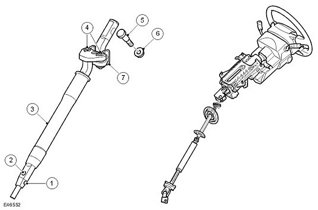
| Item name | Spare part catalog number | Description |
| 1 | - | Centering groove |
| 2 | - | Mounting hole |
| 3 | - | Cuff |
| 4 | - | Load limiter pins |
| 5 | - | Cam bolt |
| 6 | - | Self-locking nut |
| 7 | Retaining spring |
CAUTION: When handling the intermediate shaft, be careful not to hit it or dislodge the retaining spring.
The design of the intermediate shaft does not depend on the location of the steering. Its upper part is attached to the steering fork on the lower shaft of the steering column assembly. The intermediate shaft consists of two parts - the upper and lower axles, connected by overlapping.
The top axle has a cutout designed for the cam bolt. The cam bolt can only be installed when the shaft is correctly positioned in the pivot fork. A self-locking nut is installed on the cam bolt. The torque when tightening the nut turns the bolt, causing the cam to press against the shaft and correctly position it in the pivot fork before the connection is locked.
NOTE: If for any reason the self-locking nut is removed, it is recommended to replace it with a new matching nut to ensure optimum cam bolt torque.
The lower axle has a molded plastic collar that provides a surface for the plastic bearings to fit into the two bulkhead seals. The lower portion of the lower axle is double-D shaped with a tapered end. One end of the cone has a groove to align the intermediate shaft and the lower telescopic shaft, ensuring the correct relative position of the steering wheel and steering gear. The end of the double-D axle has a drilled hole to secure the intermediate shaft to the lower telescopic shaft.
The upper and lower axles are connected by a load limiter. The load limiter decouples the upper and lower axles in the event of a severe frontal collision, preventing the steering column from being overloaded and from being thrown into the passenger compartment, causing the airbag to deploy improperly.
The load limiter consists of two plates, which are parts of the upper and lower axles. The plates have a central guide pin and two mounting pins that pass through bushings in the plates, onto which a rubber and steel washers are riveted. The size of the riveted part determines the force at which the lower axle separates from the upper axle. The load limiter also has a wire retaining spring.
The article was copied from this resource: LRman.ru
Comments on this article