| Item name | Spare part number | Description |
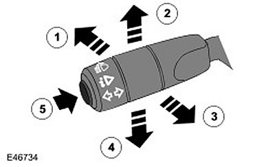
| 1 | - | high beam |
| 2 | - | Right direction indicator |
| 3 | - | High beam signaling |
| 4 | - | Left turn signal |
| 5 | - | Computer function button |
The turn signal switch assembly is installed on the left side of the housing and is attached to it with two screws. The switch is connected to the main wiring harness through a connector located on the back of the switch. The switch controls the following functions:
- Switching on the left / right turn signal
- Switching low / high beam headlights
- High beam signaling
- Selecting computer functions (in the presence of)
Direction indicators
The inclusion of the right direction indicators is performed by moving the lever up, and the left ones - down. The switch locks the lever in the selected position until it is moved to the center position where the turn signals are off. The switch has the function "rebuilding", which allows you to operate the switch without latch, which is convenient when changing lanes on the motorway and when overtaking. When the lever is released from the position "rebuilding" the switch automatically returns to the center position. Separate wires are used to turn on the left and right turn signals, connecting the switch to the central electrical junction box (CJB). When the switch is moved to a certain position, the corresponding circuit in the CJB is grounded through the switch. The CJB senses a shorted circuit and turns on the appropriate direction indicators until the switch returns to the center position. The direction indicators are turned off either manually by the driver or automatically when the steering wheel is returned to the center position.
Switching low / high beam headlights and signaling high beam headlights
To turn on the high beam headlights, the switch is moved forward. The switch is locked in this position and the high beams remain on until the driver pushes the lever back. To signal high beam headlights, the switch is moved back. The switch contacts complete the circuit and the headlights remain on as long as the lever is held in this position. In this position, the switch is not latched and the headlights turn off when the switch is released and returned to the off position. The headlight high and high beam signaling positions use separate wires connected to the CJB and ground. When the switch is set to a certain position, a circuit is closed between the CJB and ground through its contacts.
Computer function button (in the presence of)
This button is only available on vehicles with a high-level instrument cluster. The computer functions button is located on the end of the switch lever. The button is a momentary switch with which the driver can select the information shown on the instrument cluster message center display:
- Travel distance
- The distance that a vehicle can travel to run out of fuel remaining in the tank
- The amount of fuel in the tank
- Average fuel consumption
- Fuel consumption for the entire period of operation of the car
- average speed
- Instant fuel consumption
The button is connected to the instrument panel and ground. When the button is pressed, the circuit is closed and the instrument panel displays the following on-board computer reading. Pressing the button repeatedly cycles through the information shown on the message center display. For more information, please refer to the Information and Message Center (413-08 Information and Message Center).
Comments on this article